The three-phase AC system is basically designed by two different electrical connections. One is the star connection and the other is the delta connection.
These two connections have different specifications and used to achieve different functionalities. Here, I am describing the what is the difference between star and delta connection in 3 phase system.
This is one of the most important questions. And it has been asked in many of the exams and job interviews. So being an electrical engineer, you must know all the basic concepts and differences between them.
Let’s compare the star and delta wiring in tubular form.
Star Connection vs Delta Connection
| # | Content | Star Connection | Delta Connection |
| 01 | [Definition] What are the star and delta connections? | In a three-phase AC connection, one terminal from each winding is connected to a common point, and the remaining three terminals are connected to the external circuit. This connection is called as ‘Star connection’. | In a three-phase AC connection, all the terminals of each winding is connected to each other. This connection is called as ‘Delta connection’. |
| 02 | Called as | Sometimes, it is called as a ‘Wye connection’. | It is also called as a ‘Mesh connection’. |
| 03 | Representation of star & delta connections | Star connection is represented by the ‘Y’. | Delta connection is represented by the ‘Δ’. |
| 04 | Common Point connection | The common point occurs in star connection or wiring. Sometimes, this point is called a ‘Neutral point’ or ‘Star point’. | Common point does not occur in delta connection or wiring. |
| 05 | How many wires are in a three phase system? | It requires a three-wire three-phase AC system and a four-wire three-phase AC system. | It requires a three-wire three-phase AC system. |
| 06 | What is the relation between phase and line voltage? | Line voltage is equal to root three times of the phase voltage. Represent as, VL = √3 VP. | Line voltage is equal to the phase voltage. Represent as, VL = VP. |
| 07 | What is the relation between phase and line current? | Line current is equal to the phase current. Represent as, IL = IP. | Line current is equal to root three times of the phase current. Represent as, IL = √3 IP. |
| 08 | Which type of connection is used in transmission and distribution power lines? | Only in the distribution system, a star connection is used. | In the transmission and distribution system, delta connection is used. |
| 09 | Required voltage for star and delta wiring | Each winding receives 220V or 230V in star connection. | Each winding receives 414V or 415V in delta connection. |
| 10 | Distance | For the short-distance, the star network is used. | For the long-distance, the delta network is used. |
| 11 | Number of turns | It requires a large number of turns. | It requires the less number of turn. |
| 12 | Insulation | More insulation is required. | Less insulation is required. |
13. Circuit Diagram of Star and Delta connections
- Star Connection or Wiring
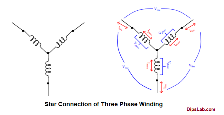
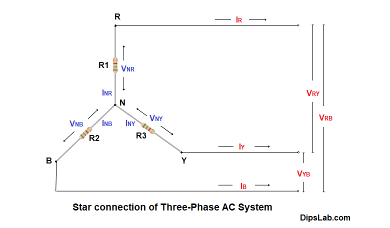
In a star connection of three-phase winding, all coils are connected at a common point. This point is called as Star point Neutral (N).

The above star wiring represents the relationship between the phase and line of voltage and current.
Line current and Phase current in delta connection:
- Line current is represented by IR, IY, and IB
- Phase current is represented by INR, INY, and INB
Line voltage and Phase voltage in delta connection:
- Line voltage is represented by the VRY, VYB, and VRB
- Phase voltage is represented by VNR, VNY, and VNB
Circuit diagram of star connection.

- Delta Connection or Wiring
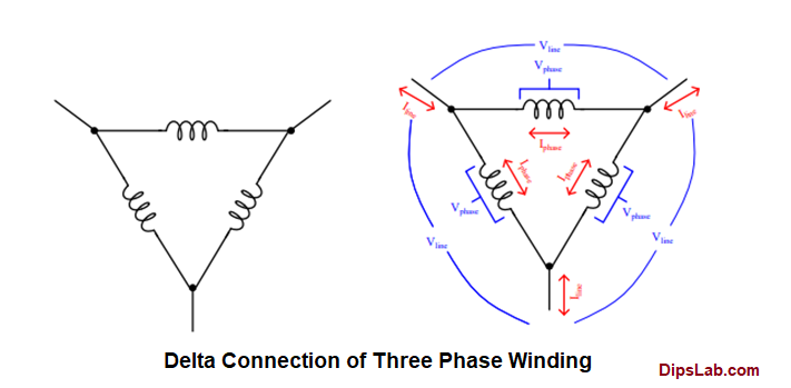
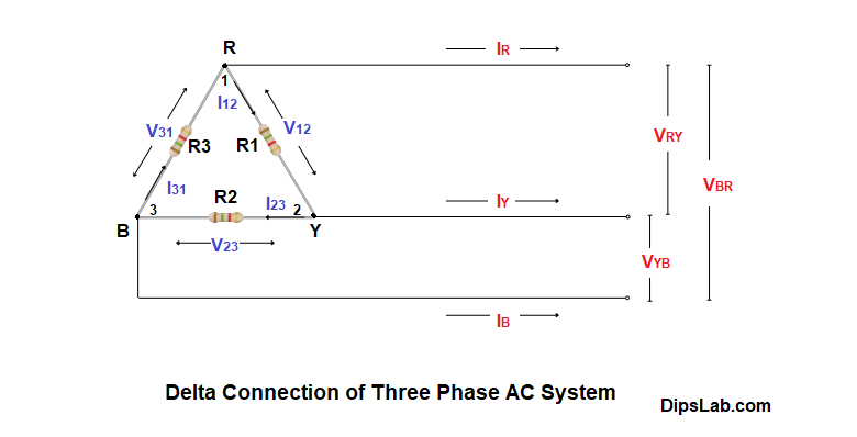
In a delta connection of a three-phase winding, all coils are connected back to back arrangement.

From the above delta wiring, we will see the the relationship between the phase and line of voltage and current.
Line current and Phase current in star connection:
- Line current is represented by IR, IY, and IB
- Phase current is represented by I12, I23, and I31
Line voltage and Phase voltage in star connection:
- Line voltage is represented by the VRY, VYB, and VRB
- Phase voltage is represented by V12, V23, and V31
Circuit diagram of delta connection.

Note: Blue remarks represent phase quantities. Red remarks represent line quantities.
This is all about the basic specifications of star connection vs delta connection. These specifications also describe the advantages of star and delta connections.
We will see the drive line and phase relationship of voltage and current for star and delta connected three phase system in an upcoming tutorial.
If you have any queries regarding the comparison between star and delta connections, drop your comment below.
Other Related Comparisons:
- Single-phase vs Three-phase AC systems
- Underground cable vs Overhead line
- AC transmission vs DC transmission
- Core transformer vs Shell transformer
- Active power vs Reactive power
- Alternating current vs Direct current
- Synchronous motor vs Induction motor
Thanks for Reading!
Very useful
Thanks 🙂
Thanks, for posting.
🙂 🙂
Thanks, Mam.
Good basic information
Thanks 🙂
Love this
Thanks 🙂
Very useful
Thanks, Tejasvinee.
Thank you.
Great explanation of the differences between star and delta connections! I found the examples very helpful in illustrating their applications.
Thanks, Mack for your kind words. I’m glad you found the explanation and examples helpful.