The Power Supply device, like other electrical parts, has its electrical characteristics and specifications, which you must know precisely when we want to buy or deal with it.
So we will review a set of technical specifications that must be taken into account when choosing that product from the leading Meen Well company to suit our needs, or so that we can use it optimally to avoid any harm.
To know, read the article below.
Introduction to the Power Supply
A power supply is an electrical device that supplies electrical energy to a load, used with the purpose of converting electrical current from the power source to the correct voltage, current, and frequency to operate the load.
So it is sometimes called ‘an Electrical Power Transformer‘, some power supplies are in the form of separate stand-alone equipment, and others are built into load devices that are powered such as in desktop computers and consumer electronics.
Voltage rise leads to the maximum permissible load in the load, and emergency energy storage under the load in the event of an interruption. temporary in the source.
Concepts in Power Supply
In this paragraph, we will explain the most important specifications and specifications of the device from Meen Well company, and we will introduce you to the working principle of the device and its internal structure.
Inruch Current
Inruch current is a large pulsating current that is generated at the moment the generator is connected to power and then returns to the normal rating, and its value ranges from (100A ~ 20 according to the design of the SPS).
Concept of Power Factor PFC
The power factor is an improvement in the ratio of the apparent power to the real power that determined the real use of electricity, and its value is about 0.4 ~ 0.6 in non-PFC power supplies, while the power supplies in it exceed 0.95.
The apparent and real power are calculated as follows:
Apparent power = (Input voltage x Input current) (Unit- VA)
And
Real power = (Input voltage x Input current x Power factor) (Unit- W)
In fact, the power plant needs to generate more power than the apparent power in order to provide electricity steadily. If the power factor is 0.5, the power plant needs to produce more than 2WVA to meet the real use of 1W, but if the power factor is 0.95, the power plant needs only to generate more than 1.06V to achieve the same amount, so the saving efficiency is greater by using the PFC function.
Power Signal Indication and Power Off Concept
Once the output of the provider reaches 90% of the rated voltage, it sends a 5V TTL signal within 10-500 ms time it is “Good Power”, and before the output becomes less than 90% of the rated voltage, at least 1 ms good power signal stops it is “Power Fail”, both of which are used for the purpose of monitoring and controlling.
Switch Time Concept
Switching time is defined as the period of time during which current flows from one end to the other and is less than 5% of the Vo change, as in UPS when the inverter switches its power supply from city power to battery power to keep the AC output voltage accurate.
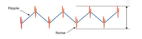
Ripple and Noise Concept
Ripple is the small, unwanted periodic variation of alternating current (AC) that appears on the DC output when the power supply is switched internally, its frequency equal to the switching frequency.
As for noise, it is a manifestation of the parasites inside the power supply, which appears in the form of high-frequency voltage spikes on the output voltage, resulting from the rectification of the sine wave, and its value is twice the value of the input frequency.
Concept of Load Voltage
Indicative of a Hi-Pot test or wattage test, this test is used to check the integrity of the insulation between the primary and secondary winding, thus protecting the S.P.S. From damage when exposed to the high voltage between the inputs and outputs.
To complete the test, the test voltage should be increased from 0V to the specified level gradually over a period of more than one second and left at the specified level for 60 seconds, but in cases of mass production, the rise time should be reduced to one second.
But before testing, the inputs and outputs must be shorted, so that the test continues within a certain loop such as I/P-O/P, I/P-FG and O/P-FG at a certain high voltage value for one minute.
When testing with alternating current, the typical leakage current flowing through the insulation material at the moment of application of the test voltage is 25 mA, if its flow increases rapidly, this means the insulation has collapsed.
In this case, the Y capacitors are the main cause of the leak, as the 4.7nF capacitor causes a current leakage of 5mA as per UL-554 regulations, they should be removed when testing, but in mass production cases, this is not possible so they increase the leakage current setting of the test instrument.
The test voltage is replaced by DC when there are bridge capacitors between primary and economical circuits as per IEC60950-1 regulations.
Types of Power Supplies
There are several types of power supplies according to the output voltage or the current of each of them:
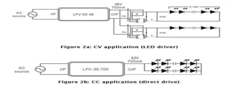
- Type CC In this type the output voltage is uniform and stable, and the input of each load varies (90″264VAC).
For example: LPV-60-48 power supply used (LED drive + LED string) keeps 48V value on its output. - CV type This type gives a constant output current, while the output armature is equal to the sum of the VF of the LED group.
For example, If we use a series of 12 LEDs, with a voltage of Vf=3.5V and a current of 350mA for each LED, the total voltage is 3.512=42V, but if we have two series in parallel, the total current is IF=3.52=700mA - Type CC+CV This mode has the characteristics of both types together, during startup it works in CV mode suitable for Series resistor and LED driver IC applications. The output current exceeds the standard current of the power supply, reaches the DC area and the device stays in the DC mode that is suitable for direct drive.
- Constant power design
The constant power method in the LED drive is the same as the constant current principle, the maximum power in the general DC condition is held only at one output voltage and one output current.
Constant power LED drive gives flexible and efficient LED voltage and current, optimized size and stock.
How to Control the Operation of the Cooling Fans?
Cooling fans have a relatively shorter life compared to other components, so the way the fans operate affects the prolongation of operating hours, and the fans are controlled by two systems:
- Control in temperature: When the internal temperature of the power supply is higher than the minimum, the fan runs at full speed, but if it is below the set threshold, the fan stops working or runs at half speed.
In some equipment, the fans are controlled non-linearly, as the fan speed can be changed at different temperatures simultaneously.
- Load control: exceed load Power supply minimum The fan starts to run at full speed, but if the load is less than the specified limit it stops working or runs at half speed.
Overload or Overcurrent Protection Methods
The protection circuit operates when the current drawn exceeds the rating of the PSU, and it is divided into several forms, namely:
Current Foldback
In this case, the output current is reduced by about 20% of the rated current.
Current Continuous Selection
In this case, the output current is fixed at one level of the specified range, and the output voltage is reduced.
Reducing Excess Energy
The output power remains constant, and when the load increases, the output voltage decreases proportionally to it.
Determine Current Hiccups
In this case, the output voltage and current remain on and off repeatedly when the protection is activated, and return to normal after it is removed.
Closure
In this case the output voltage and current are cut off when the load reaches the protection range.
Restart states
When the power supply is turned on, the motor overload operation (OLP), to avoid the output power rating adjustment or OLP point, the second over-temperature protection (OTP) second, the temperature reaches the internal value and has appeared, will enter the mode and shutdown mode, once it is gone back to normal.
How to Restart PSU?
- Auto Recovery: The PSU will restart automatically.
- Manual recovery: Here the PSU restarts by manually restarting the AC.
It is necessary not to operate the PSU in case of overcurrent or short circuit for a long period of time as this will shorten the life or damage the supply.
Difference Between Directors- V and COM
COM (COMMON) means common pole, there is multiple output supply positive (V1+, V2), negative (COM), while in one output power supply positive (V1+), negative (V1-).
Difference Between MTBF, Life Cycle and DMTBF
MTBF and life cycle are both indicators of reliability in any power supply device, but the difference is:
The MTBF is the duration of proper continuous use of the power supply for a specified period.
That is, the continuous operation of the provider correctly during the specified time MTBF is 36.8% (e-1 = 0.368), and if the time of MTBF is doubled, the probability of proper operation is 13.5% (e-2 = 0.135).
MTBF is calculated by two methods namely ‘part number’ and ‘stress analysis’ by MIL-HDBK-217F Notice 2 and TELCORDIA SR/TR-332 (Bellcore) regulations.
Currently, MEAN WELL relies on MIL-HDBK-217F regulation stress analysis, Life Cycle i.e. the approximate life of the supplied, calculated by the temperature rise of the electrolytic capacitor below its maximum operating temperature, for example
RSP-750-12 MTBF = 109.1 thousand hours (25 ° C), electrolytic capacitor C110
cycle life = 213K hours (Ta = 50 ° C)
DMTBF Displays the mean time between failures, it can assessing MTBF。, and can calculate it from the relationship.
Total test time= (MTBF*X 2) / (2*N*AF)
Where,
- MTBF- Mean Time Between Failure
- X2 can be found in the chi-square distribution
- N- number of samples
- AF is the acceleration factor, which is derived from the acceleration factor equation.
MTBF COMPARISON OF MEAN WELL WITH A COMPETITOR PRODUCT
There is no dispute about MTBF calculation, while the dispute lies in MTBF version, component fatigue, and component count, MEAN WELL also it doesn’t sell private brand standard power supply as other OEM/ODM companies, so MTBF is not able to customize.
MEAN WELL is still striving for the best, and has rechecked the MTBF parameters of TELCORDIA SR / TR-332 (Bellcore) and done the improvement, has revised the supplier’s quality policy and accompanied with IQC / OQC / FQC…etc.
The reason why the LED of the AC IN stops after the voltage is applied to the inverter TN-1500
When the inverter is in UPS mode and the mains voltage drops by more than 5% of the specified AC output voltage, the inverter switches its power supply from city power to battery power to keep the AC output voltage accurate, so the AC IN indicator on the inverter front panel is turned off.
Where, The output of the 110VAC inverter is switched to 100/110/115 / 120VAC, the same as the output of 220VAC to 200/220/230 / 240VAC.
Main Difference Between 1~10V and 0~10V Dimming
Both of them are related in the luminaire, but with type 1~10V the luminaire can be dimmed to 10%, and the type 0 ~ 10V can be dimmed to 0, “off”.
Difference Between a Single-Phase and Two-Phase Supply
In a single-phase power supply both of the functions of power factor correction and transformer, there are in a single circuit, while dual-phase uses two separate circuits.
A two-phase supply is more complex and expensive, has better AC mains immunity than a single-stage supply, and has better performance for ripple noise on the output.
While the single-phase power supply features low cost, simple layout, and high efficiency in small power applications.
Choose Product Stae
After we talked about the most important concepts and technical specifications of the Power Supply device, we will move on to how to choose a device that suits our needs.
Observe the IP Protection Standards of the Power Supply
The company has integrated dust and water suppression into most of the LED power supplies according to the international standard IEC60529, but not all the power supplies can be submerged in water, for installation restrictions see the table:
IP64 rated feeders are suitable for indoor or outdoor applications in protected locations, IP64-IP66 and IP67 ratings are suitable for potentiometer products suitable for an indoor or outdoor protected environment.
Considering the Current Accuracy of LED SPS
The accuracy of the LED SPS output current can be obtained from the product specifications, for the CC model you can find it in the specifications section, for the CC + CV model you can find it in the protection section of the specifications section.
How to Choose cc or cv Power Supply?
Constant-Voltage (cv) Power Supply
It is widely used in power supplies for electronic circuits, where most electronic circuits are designed to operate at a constant voltage because they cannot operate properly if the voltage fluctuates in an unintended manner.
Constant-Current (cc) Power Supplies
Constant-current power supplies are used to power LED lighting and charge rechargeable batteries.
The brightness of LED lighting is determined by the current value, so if the current value fluctuates, the brightness will change accordingly, so a stable current is required.
Also, when charging rechargeable batteries, the voltage and current are not proportional due to the characteristics of rechargeable batteries, Therefore, a constant current power supply is used so that the current is supplied regardless of the voltage applied to the battery.
Constant Power Supply
Use with variable load. Using a load monitoring IC that senses the load current and load voltage independently, and amplifies the corresponding signals with the internal analog multiplier, applying the multiplier’s output to the inverting input of the error amplifier allows you to apply a control voltage to set the constant power level.
For example, when the load resistance is not constant, this is the problem with keeping the LCD screen warm on an external gas pump in cold climates. When the heating element changes temperature, its resistance also changes which complicates constant power delivery. The variation in resistance is characterized by the temperature coefficient of the heating element. If you apply a constant voltage, the power delivered to the load varies inversely with the load resistance, so you must allow the applied voltage to vary with the load resistance.
How to Choose a Single-Phase or Two-Phase Power Supply?
The single phase is suitable for fields with high-quality AC mains but in dangerous conditions such as industrial switching power sources, a two-phase supply must be used.
Things to consider when buying an IP67 product
It must be ensured that IP67 is equipped with ADJ functions. Based on the design of the potentiometric mechanism, the protection is not as perfect as the non-containing type, so it is recommended to choose the BLNK version when the application is not protected.
Choosing a Reliable Switch Power Supply
To choose a highly reliable sps device, several things must be considered and taken into account:
- Device Capacity: You should choose a power supply with a capacity that is 30% larger than the actual requirement of your system.
- Ambient temperature of the device: If the device is in a place with a high temperature, and there is no additional cooling device, some of the energy generated from it must be reduced,
and you can find the relationship between temperature and output energy in the device’s technical bulletin. - Choosing the functions of the device to suit your needs: Here we will mention the available functions and how it can be set it:
As for the protection function, you have several options for protection from current, load or overheating (OVP, OLP).
As for the special function, you have two options, UPS, PFC, that is, using it as a power rectification factor or a supplier in the event of a power outage.
As for the function of the application, the options available here are the signal function (good strength, power failure), remote control, remote sensing, and others. - Ensure that the model qualifies for safety standards.
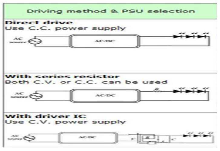
Selection of Power Supply according to LED Driving Methods
There are several ways to operate the LEDs via the power supply, which are:
- Direct connection: CC type supply can be used, here the supply output voltage is equal to the total LED VF, IF will affect the temperature change, the current is uneven for the parallel LED series, the price is lower, and the efficiency is high, the luminance is rapidly reduced, the life of the LED is short.
- Connection using resistors: CV or CC type supply can be used and here the voltage exceeds LED VF total will appear across the resistance series, IF medium, a lower price with additional resistors cost, lower efficiency, lower resistance power, medium IF stability.
- Connection using IC: CV type supply can be used, here IC reduces IF for each LED string, LED life is long, high efficiency, lower efficiency, slow luminance drop, and high IF stability.
MW LED power supply selection method allows V/I . adjustments
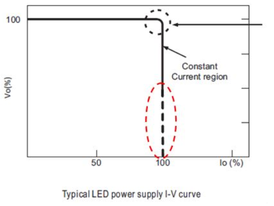
A provider is selected according to the type of modulation required, the allowable modulation range can be determined by the specification sheet, and the level of both voltage and current is adjusted using VR devices or built-in potentiometers. How can read LED dotted lin V-I
The section that is not suitable for LED applications is represented by a dotted line, and according to the protection criteria we can classify it into hiccup mode and DC mode.
The differential mode model is chosen if you do not want to see a very high current when a short circuit occurs, and the DC mode is suitable for applications where motors or capacitive loads.
How to Choose a Suitable MW LED Power Supply?
When choosing a menweel MW LED power supply, you should consider several points:
- Determining the appropriate wattage based on your system requirements and application methods, and the increased wattage and driving method must be considered, and here you
have two options:
When using a MW power supply with a direct actuator, the combined forward voltage field of the LED (upper and lower) must be within the DC voltage range of the LED power supply.
For example
If we have LED Vf has specifications 3.4 ~ 3.6V, and when you connect 6 LEDs in series, the total Vf will be 20.4 ~ 21.6V, so you should choose a 24V module with a constant current area of 18 to 24V.
and in the areas where The alternating current voltage is unstable such as heavy industrial area or generator supply facilities, LED string should be chosen for general use.
- when using an MW power supply with LED driver IC to achieve high precision current control, the starting voltage of the driver IC should be as close to the rated voltage of the power supply as possible.
While the driver IC needs a constant voltage to function properly, so you can use it the general usage series, in this kind a potential problem may appear in the EMI system, so after the design of the lighting system is finished, it is necessary to double-check the EMI.
For models with PFC requirements and system PF > 0.9, the load utilization should be higher than specified in the PFC specification, typical requirements are 75% load or higher, double-check the specifications of the model you are using to confirm the actual requirements.
- Select the appropriate IP level and mechanical type(Metal enclosure, plastic cover) Depending on the operating environment of the LED power supply.
- PFC function selection determination
Single-phase PFC is only suitable for LED load, and two-phase is suitable for general applications.
- If the LED system is based on the direct drive method, then units with adjustable voltage and current should be considered for flexibility in changing V/I levels.
- If you want to control in LED brightness, should choose a power supply with a dimming function.
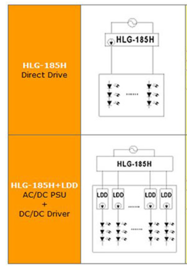
Selection of HLG-185 and HLG-185+LDD
HLG-185 and here the connection is Direct driver This type is characterized by lower price, simpler design, a fault in one chain will affect another, no current balance in each chain.
HLG-185+LDD and here AC/DC PSU +DC/DC driver connection of this type has a higher price, independent output current balance in each chain and the occurrence of a malfunction in one of them does not affect the other, additional space must be provided for the installation of ldd.
After you choose the product you want and buy it, you need to have an idea of how to use it, we’ll talk about that in the next paragraph.
Stage of use
In this paragraph, we will guide you on how to properly connect and operate the power supply device and point out the things you should take care of.
How to Connect AC & DC at the Input Side?
The inputs of MEAN WELL power supplies are of three types according to their design:
a.85~264VAC;120~370VDC
b.176~264VAC;250~370VDC
c.85~132VAC/176~264VAC by Switch; 250~370VDC
In models, a and b the positive pole connects to AC/L, and the negative pole connects to DC/N, others may require an opposite connection.
For Model C, 115/230 V must be connected correctly, if the switch is on the 115 V side and the real input is 230V, it damages the power supply.
Pay Attention to Operating Parameters
The frequency range that the power supply operates at is 45Hz ~ 440Hz, if the frequency is too low, the efficiency will also decrease, if the frequency is too high, the power factor of S.P.S with PFC function will decrease, resulting in higher leakage current.
For example when the SP-200-24 is operated under 230VAC and rated load and the AC input frequency is 60Hz the efficiency is about 84%, the power factor is 0.93 and the leakage current is about 0.7mA.
If it decreases to 50 Hz the efficiency becomes about 83.8%, and when the AC input frequency increases to 440 Hz, the power factor will decrease to 0.75 and the leakage current will rise to about 4.3 mA.
Observe the Minimum Load
To allow the multi-outlet power supply to work properly, it is necessary to have a minimum load for each output of his outputs, otherwise, the output voltage level will be unstable, you find the minimum load in the specification table.
Inruch Current Effect
Although the inrush current will not damage the power supply, it is better not to turn the power supply on or off too quickly within a short period of time.
Also if you have more than one power supply running at the same time, the transmitting system of the AC source may be shut down and go into protection mode due to the huge inrush current, it is better to start these feeders one by one or use the remote control function of S.P.S. to turn it on / off.
Ripple Current Measurement
By Digital multimeter, the red meter’s sensors are connected to the positive terminal and black to the negative terminal, likes to choose the AC mode by rotating the pointer, this is how the meter measures.