
In an earlier tutorial, I have described the corona in power system with it’s affecting factors and disadvantages.
In this tutorial, let’s study…
- What is the Surge Impedance Loading?
- What is the Ferranti Effect in Transmission Line?
- How to reduce the Ferranti Effect in a transmission line?
I will also explained you the surge impedance loading formula to calculate numerical problems.
Let’s begin.
Table of Contents
Surge Impedance Loading
Surge impedance loading (SIL) indicates the maximum power that can be transferred through the transmission line without any consequences.
This totally depends on the surge impedance of the line. The surge impedance of the line can be calculated as:
As we know that the transmission line has the distributed component of inductor ‘L’ and capacitor ‘C’.
When the transmission line is charge at that time the energy transfer takes place between the inductor and capacitor. This energy exchange will be mutually shared by inductor and capacitor and finally, the required energy is transferred to the receiving end.
The distributed parameter of the transmission line is represented with the lumped network for further analysis as shown in the below figure.
This energy collaboration between the capacitor and inductor is shown below.
Energy stored in the capacitor, Ec = [(1/2) × C × V² ]
Where,
C – Equivalent distributed capacitance of the line
V – System voltage of the transmission line
The store energy in the inductor is given by-
Energy stored in inductor, EL = [(1/2) × L × I² ]
Where,
L – Equivalent inductance of the line
I – Load current
As we know that, when the Ec and EL are equal then the maximum true power transferred through the transmission line, and the impedance that comes out from this energy exchange is called as ‘Characteristics Impedance (Zc)‘ or ‘Surge Impedance (Zs)‘.
Energy stored in the capacitor (Ec) = Energy stored in inductor (EL)

                              [(1/2) × C × V² ] = [(1/2) × L × I² ]
By solving,
(V/I) = √(L/C)

Zs = √(L/C)
With the help of the above surge impedance loading formula, we can find out ‘Zs’ by using online Surge Impedance Calculator the of any line.
This calculator is very much handy for surge impedance loading calculations of numerical problems.
From this surge impedance, the value of surge impedance loading (SIL) can find out before designing any transmission line.
The surge impedance loading of transmission line is also referred as a steady-state power limit.
The steady-state power limit can be determined as follows, with the help of conventional receiving power transformation formula,
Pr = (Vs² / Zs)
This is maximum real power transfer by any transmission line and called as ‘Loading of Line‘ ( or Surge impedance of the line).
With this, hope you are clear with difference between surge impedance and surge impedance loading.
Ferranti Effect
Ferranti effect is the effect that will occur mostly in the long transmission line. For short and medium transmission lines it is negligible.
When the receiving end load of the transmission line is not connected (No load) or operates at low load conditions then the capacitance of the line produces more reactive power which is more than the inductance of the line required.
And under this condition, the receiving end voltage (Vr) is more than the sending end voltage (Vs) and it is called as a ‘Ferranti effect‘.
We can consider in another way as ‘ When the loading of the line is less than the surge impedance loading the additional reactive power produced by the capacitance of the line increases the receiving end voltage referred as a ‘Ferranti effect in transmission line’.
To understand the Ferranti effect the distributed network of the transmission line is converted into the lumped network with a simple circuit.
As there no load or for the lightly loaded condition the capacitive reactance of the transmission system allows the flow of current which is of the leading power factor(Ic).
This current will create the drop in the reactance and resistance which is the phase opposition to that of the receiving end voltage.
This can be illustrated with the help of phasor diagram as shown below.
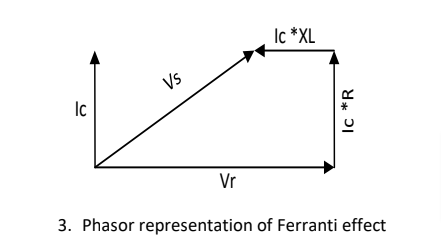
From this, the vector magnitude of ‘Vr’ is more than the ‘Vs’. So this way we can also represent the Ferranti effect in transmission line.
How to reduce the Ferranti Effect?
For the Ferranti effect, transmission line creates the more leading reactive power due to capacitive effect present in the line.
This can be mitigated by the use of a shunt inductor. So, the generated reactive power would be absorbed by the inductor and finally make the balance of the reactive power and it will minimize the Ferranti effect.
Read some related tutorials:
- AC Transmission vs DC Transmission
- Overhead Lines and Underground Cables
- Transmission Line vs and Distribution Line
- Single Phase vs Three Phase AC System
- Reactive Power Compensation
- Components of Overhead Lines in Transmission & Distribution
- On-Grid System vs Off-Grid System