In an electrical and electronic circuit, multiple electronic devices are used or connected in the form of energy source and load.
These devices help to build an electrical circuit. And it completes the current path for generating electricity.
Let’s study an electrical source and load in detail.
Table of Contents
What is Electrical Sources?
The source which generates the electrical power or energy is called as ‘Electrical Source’.
For the generation of electrical power or electricity, renewable and non-renewable sources are mostly used. The sun, wind, water, coal, oil, nuclear energy are the best example of renewable and non-renewable sources.
It produces electrical energy in the form of electric current and voltage.
What are the different types of Electrical Sources?
Electrical sources are classified into two main categories.
1. Voltage Source
The voltage source is also classified into two sub-categories.
- Ideal Voltage Source
- Practical Voltage Source
2. Current Source
The current source is also classified into two sub-categories.
- Ideal Current Source
- Practical Current Source
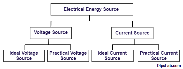
Classification of Electrical Energy Source
Here is explaining the classification of electrical sources one by one.
What is the Voltage Source?
The device or source which generates and maintains potential energy is called as ‘Voltage Source’.
The symbolic representation of the voltage source is-

Battery and generator are the daily life example of the voltage sources. From voltage source classification, Ideal voltage source and Practical voltage source are classified.
Now we will study, what is the Ideal Voltage Source and Practical Voltage Source?
1. Ideal Voltage Source
The ideal voltage source is known as ‘an Independent Voltage Source’. Because, it provides a constant terminal voltage across any variation of load.
In an ideal voltage source, the internal resistance is always zero. Due to the zero internal resistance, the input voltage source (Vin) and load voltage (Vout) is the same.
Calculation of Ideal Voltage Source: The value of an ideal voltage source calculate by the following formula.
Volatge Source (Vs) = (Vl) = (Il * Rl) (Unit- Volt)
Where,
(Vs- Source Voltage), (Vl- Load Voltage), (Il- Load Current) and (Rl- Load Resistance).
2. Practical Voltage Source
Practical Voltage Source is also known as ‘Dependent Voltage Source’ or ‘Controlled Voltage Source’.
Calculation of Practical Voltage Source: The value of practical voltage source calculate by the following formula.
Load Volatge (Vl) = [(Vs) - (Il * Rs)] (Unit- Volt)
Where,
(Vs- Source voltage), (Il- Load Current) and (Rs- Source resistance).
What is the Current Source?
The device or source which generates charge particles or electric current is called as ‘Current Source’.
The symbolic representation of the current source is-

It consists of two sub-types like ideal current sources and practical current sources.
Let’s study, what is the Ideal Current Source and Practical Current Source?
1. Ideal Current Source
Ideal Current Source is basically known as ‘Independent Current Source’.
The source which provides a constant current to the load by changing the across load voltage (Vl) or load resistance (Rl) this source is known as ‘Ideal Current Source’.
Calculation of Ideal Current Source: The value of an ideal current source calculate by the following formula.
Current Source (Is) = (Il) = (Vl / Rl) (Unit- Ampere)
Where,
(Is- Current Source), (Il – Load Current), (Vl – Load Voltage) and (Rl – Load Resistance).
2. Practical Current Source
In the practical study, the source current is not getting the same load current due to the different load or variable resistance.
Calculation of Practical Current Source: The value of practical current source calculate by the following formula.
Load Current (Il) = (Vl / Il) = (Is - Ish) = [Is - (Vl / Rsh) (Unit- Volt)
Where,
(Vl- Load Voltage), (Is- Source Current), (Rsh- Internal Resistance) and (Ish- Current in Internal Resistance)
This is the explanation of current and voltage (an ideal and practical) source.
What is an Electrical Load?
The electrical load is used to transform and store energy to other applications.
It is classified into different types like inductive, resistive or capacitive in the form of the various electrical and electronic applications. For example, Motors, Lamp or light, Heater, etc.
With load and without load condition:
- At load condition, power source and load are connected to form completed path for flowing electrical current. This complete circuit is called as ‘Closed Circuit’.
- At no-load condition, power source and load are not connected to each other. So, the zero current occurs at no-load condition. This circuit called as ‘Open Circuit’.
Electrical Circuit Element
Basically, an electrical circuit elements are classified into different types.
- Active Element
- Passive Element
- Linear Element
- Non-Linear Element
- Unilateral Element
- Bilateral Element
We will learn each part of the circuit elements with an example.
1. Active Element
An electrical element which can be having own capability to produce the current in the circuit is called ‘an Active Element’.
It simply called as Electrical Source. This element helps to produce increasing the level of energy in the circuit.
Battery, Generator, Alternator, and other electronic components (LED, Diode, Transistor, Integrated circuit (IC’s), Vacuum tube) these are an example of the active elements.
Note: A circuit having at least a single active element for flowing current and producing voltage.
2. Passive Element
The elements which can restrict, store and supply the energy to others from the input source is called ‘Passive Element’.
In passive elements that do not produce own their energy. And it occurs in the form of a Load.
Resistor, Switches, Voltmeter, Ammeter, Transformer, Capacitor and Inductor (coils), these are the example of the Passive element.
In passive circuit does not work due to the absence of power sources. So, it must provide or connect the input source.
3. Linear Element
A linear element is also called as Ohmic Element. Because, this circuit element follows Ohm’s Law.
A circuit element which gives constant value with respective time while any variation in voltage or current is called as ‘Linear Element’.
It is always a Passive Element and Bilateral Element. Resistance is the best example of the linear element.
In V-I characteristics of a linear circuit, linear element (i.e. resistance) show in a straight line condition.
4. Non-linear Element
A non-linear element is also called as Non-Ohmic Element. Because, it does not follows Ohm’s Law.
A circuit element which does not gives constant value with respective time while any variation in voltage or current is called as ‘Non-linear Element’.
All active element is a non-linear element. A Diode is the best example of a non-linear element.
5. Unilateral Element
The element which allows the current in only one direction (Uni direction) in the circuit is called ‘Unilateral Element’.
A Diode is the best example of the unilateral element.
6.Bilateral Element
The element which used to flow in both directions (forward and reverse direction) in the circuit is called ‘Bilateral Element’.
The Transmission line is the best example of the bilateral element. In the transmission line, AC current can flow in the forward and reverse both directions but the not particular single path.
Electrical Circuit
Classification of the electrical circuit is basically divided into two categorize. It’s naming as,
- Series Circuit
- Parallel Circuit
1. Series Circuit
The circuit consists of various elements in a single path for flowing the same electrical current is known as ‘Series Circuit’.
In the series circuit, the same current flowing through each electrical component (maybe a source or load element).
Look here, a series circuit with connecting source and load (voltage, current, and resistance).
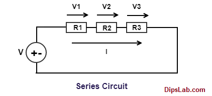
But, different voltage occurs across each connected component in the circuit.
Total Current (Ieq) = I1 = I2 = I3 =........= In (Unit- Ampere)
Total Voltage Calculation:
Total Voltage (Veq) = V1 + V2 + V3 +........+ Vn (Unit- Volt)
2. Parallel Circuit
The number of elements is connected in parallel form in an electrical circuit is called ‘Parallel Circuit’.
The voltage across each element is the same. But they have different currents in it. It having one or more paths for flowing electron with the different values of currents.
Look here, a parallel circuit with connecting source and load (voltage, current, and resistance).
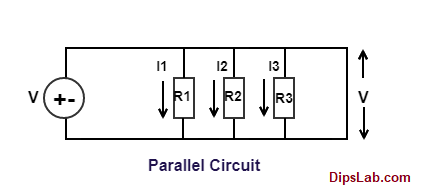
The total voltage across the component is,
Total Voltage (Veq) = V1 = V2 = V3 =........= Vn (Unit- Volt)
Total current calculation:
Total Current (Ieq) = I1 + I2 + I3 +.......+In (Unit- Ampere)
You can find out the other electrical quantities (like capacitance, inductance, impedance)value in series and parallel circuits.
Related Read: Here, you can learn more about the difference between Series Circuit and Parallel Circuit.
Basic Electrical Circuit Concepts
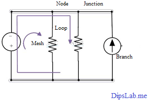
Now, I am explaining the five different (Branch, Node, Junction, Loop, and Mesh) basic concepts of an electrical circuit.
Look here, a simple electrical circuit.
 Electrical Circuit Diagram
1. Branch
A different path of the circuit which consists of only one circuit element between two terminal is known as ‘Branch’.
From the above figure, voltage source, current source, and resistor are represented single elements in the form of different branches.
2. Node
A point at which two or more elements are joints together at a single point is called ‘Node’. A node refers to two or more branches.
3. Junction
A point in the circuit at which three or more branches are joint together is called as ‘Junction’. Node gets in the center of the junction.
Note: All junction is a node but all nodes cannot be the junction.
4. Loop
A set of branches which form the closed path in the circuit is called as ‘Loop’.
5. Mesh
Mesh is typed of the loop. But loop does not occur in the mesh. All meshes are loops and all loops do not mesh.
So, in this tutorial, I try to cover all sources, load, the circuit element, electrical circuit concept with an examples.
If you have any queries, feel free to write in the comment section below.
Related Read:
- Alternating Circuit Vs Direct Current
- Electric Motor Vs Generator
- Electrical Measuring Instruments
- Basic Electrical Laws
- Single Phase Vs Three Phase
Thanks for Reading!