Based on the design of electrical circuits, they are categorized into two forms- a series circuit or a parallel circuit.
You can connect the number of electronic devices in a series or parallel connection.
With the help of this tutorial, here we are studying- series and parallel circuits. their specifications like basic definition, working role, function, use.
I will elaborate on each of these points with appropriate formulas and representation of the circuit diagram.
Let’s begin.
Table of Contents
Difference between Series Circuit and Parallel Circuit
Below is a tabular form where I’m comparing a series circuit and parallel circuit.
| Sr. No. | Content | Series Circuit | Parallel Circuit |
| 01 | Definition
(to understand the Physical circuit design refer to diagram ) |
The circuit which consists of multiple electronic components in the sequential order in a signal branch is called as ‘Series Circuit’. | The circuit which consists of multiple electronic components in the parallel branch is called as ‘Parallel Circuit’. |
| 02 | Circuit Path | It has a single path to pass current. | Current can be pass through multiple paths. |
| 03 | Construction | It can be easily constructed using less conductor. | The construction of the parallel circuit is complicated.It required more conductor. |
| 04 | Electric Current | In the series circuit, the same current is flowing through each component or load.The representation of the equivalent current is, Ieq = (I1=I2=I3=…..=In). | In the parallel circuit, the equivalent current is the sum of current passes through all the branches.The representation of the equivalent current is, Ieq= (I1+I2+I3+…..+In). |
| 05 | Potential Difference(or Voltage)
for Series and Parallel Circuit |
In the Series circuit, equivalent voltage is the sum of the voltage across all the serial connected components.Calculating the value of the potential difference is Veq= (V1+V2+V3+…..+Vn). | In the parallel connection, each branch has the same potential difference.Calculating the value of the potential difference is, Veq= (V1=V2=V3=…..=Vn). |
| 06 | Working(with Example) | If a single component is damaged, the current does not flow through the circuit.And the whole series will become useless. | If any of the components are damaged, the current will not flow through that particular branch.As current flows through other parallel branches, this circuit will work properly. |
| 07 | Maintenance | It is very complex to maintain this type of circuit. | It can be easily maintained. |
| 08 | Detection | In a series connection, fault cannot easily detect. | You can easily find out the fault condition and disconnect from the connection. |
| 09 | Repair | The series circuit is not so easy to repair as compare parallel circuit. | The parallel circuit can be easily repaired. |
| 10 | Uses (practical examples) |
It is rarely used in the circuit.Lightning series is the example of a series circuit. | It is mostly used in domestic, commercial and industrial purposes.For the domestic purpose, a parallel connection is used with constant voltage (230 V). |
11. Electrical Circuit Diagram [Series and Parallel Circuit]
In both series and parallel circuits, ohm’s law of electricity is used for calculating the value of electrical quantities.
Series Circuit Diagram:
In a series circuit connection, the number of electrical elements or components are connected in series or sequential form.
For example, the given circuit is said to be a series circuit, when electronics components (such as resistance R1, R2, and R3) are connected in a single path with a connected voltage source (Vs).
You can easily understand from a given circuit diagram.
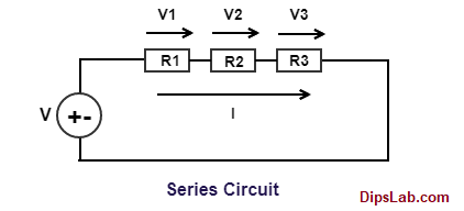
When a voltage source is given to a circuit, the same current is flowing (I). But, different (or drop) voltage (V1, V2, and V3) occurred across all the serial connected resistance.
The sum of voltage drops in individual series-connected resistance is equal to the applied voltage (i..e V= V1+V2+V3).
You can calculate the value of equivalent voltage and resistance of a series circuit by using an online calculator tool.
Voltage calculation:
Resistance Calculation:
This is a basic explanation of the series circuit.
Parallel Circuit Diagram:
In the parallel circuit connection, the number of electrical elements or components are connected in parallel form.
For example, when electronics components (such as resistance R1, R2, and R3) are connected in a parallel branch with a connected voltage source (Vs).
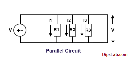
When a voltage source is given to a circuit, the same current is flowing (I). But, different (or drop) voltage (V1, V2, and V3) occurred across all the parallel-connected resistance.
The sum of voltage drops in individual parallel-connected resistance is equal to the applied voltage (i..e V= V1+V2+V3).
You can calculate the value of equivalent voltage and resistance of the parallel circuits by using an online calculator tool.
Current calculation:
Resistance calculation:
These are the main difference between series and parallel connection of the circuit.
You can calculate the total value of different components which are connected in series or parallel form by using the equivalent series and parallel calculator.
Advantages and Disadvantage of Series and Parallel Circuit
There are certain pros and cons associated with series and parallel circuits.
Advantage of the Series Circuit
- Series circuit is simple to design. You can easily build a circuit.
- It is less complex as there are no required multiple paths or branches.
- It requires fewer conductors (ex. wires).
Disadvantage of the Series Circuit
- In the series circuit, if any one component is damaged, the whole circuit will not work.
- There is more maintenance cost associated with it.
- You can not easily detect the fault condition.
Advantage of the Parallel Circuit
- We can connect different power appliances in a parallel circuit with the same voltage.
- It always works properly even any branch or component is damaged in a parallel branch.
- You can connect or disconnect the damaged part from the branch.
Disadvantage of the Parallel Circuit
- The parallel circuit requires more conductors (ex. wire) to complete the circuit.
- You can not vary the voltage in any of the parallel branches. There will be a constant voltage across all the parallel branches.
These are the advantages and disadvantages of the series and parallel circuit.
Here are some more related differences you might be interested in:
- Conductor Vs Insulator
- Alternating Vs Direct Current
- Single-Phase Vs Three-Phase
- Electrical Vs Electronic Circuit
- Electrical Vs Magnetic Circuit
If you have any point to discuss the circuit, comment below this post. I will catch you with another electrical tutorial.
Till then, Happy Learning!
Efficiently described the difference between series and parallel circuits.
Thank you, for the compliment.
Great job.
Thanks, Sangkar 🙂
THANK YOU,YOU REALLY HELP ME STUDY MORE FOR MY 8TH GRADE EXAMS.HAVE A GOOD DAY
Hi Donna, I’m really glad to found it very beneficial to you.