
Today, I am writing an article about Kirchhoff’s Laws. These Kirchhoff’s laws are most important among all the Basic Electrical Laws and Theorems.
Let’s begin.
Table of Contents
Kirchhoff’s Laws
What is Kirchhoff’s Law?
In an electrical and electronic study, Kirchhoff’s Laws are useful to determine the value of the parameter in the circuit. Finding values of these parameters help you to simplify and analyze the circuit network.
These laws can be distinguished into two parts (based on current and voltage).
- Kirchhoff’s Current Law
- Kirchhoff’s Voltage Law
Look at History (almost before 200 years)…
In 1824, these laws invented by the physics scientist “Gustav Kirchhoff”. So, the law’s name had given after his invention.
These laws operated base on the principle of ‘Conservation of Energy’.
In the electrical circuit, a number of electrical sources and loads are connected to each other. And so, it also forms the number of branches, junctions, etc.
An electric circuit consists of two types of junctions as mentioned below.
- Current Junction
- Voltage Junction
First of all, we should know-
What is the Current Junction?
In an electrical circuit, the branches of all currents are meeting at a single point. This point is known as the “Current Junction”. It is also called as “Node”.
Moving to another type of junction…
What is the Voltage Junction?
The branches of all the voltages come together in the form of a closed path or circuit. This circuit is called as the “Voltage junction” or “Loop” or “Mesh”.
Now, we are going to see the classification of Kirchhoff’s Laws.
Classification of Kirchhoff’s Laws
Kirchhoff’s Laws are classified into two main parts…
- Kirchhoff’s Current Law [KCL]
- Kirchhoff’s Voltage Law [KVL]
Let’s see the description of these two laws one-by-one.
1. Kirchhoff’s Current Law [KCL]
This is the Kirchhoff’s first law based on the current source in the electrical circuit. This law is also known as the ‘Node Law’.
Kirchhoff’s current law is stated as, ‘The algebraic sum of all currents at a node or meeting at a single point is zero’.
Let’s do some mathematics.
The equation of the current determined by using the node analysis…
For the Node,

(I1 + I2 + I3 + I4 +........ + In) = 0

The equivalent current express as,

Ʃ(I) = 0

Where,

Ʃ(I) = (I1 + I2 + I3 + I4 +........ + In)
For Example:
In the below electrical circuit diagram, electrical currents are flowing through the different components (Resistor, capacitor, and inductor).
According to the first statement of this law, we can determine the equivalent electrical current (I) of the circuit.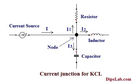
The equation can be represented as,
According to the first statment of law,

 Ʃ(I)= 0

Where, I is the total current.

(I1+I2+I3)= 0
OR
In another way, Kirchhoff’s current law is stated as “The sum of all leaving current at the node is equal to the sum of all entering current at the node”.
Mathematically can be represented as,
For the Node,

Ʃ(I) (Leaving currents) = Ʃ(I) (Entering currents)
For Example:
In the below electrical circuit diagram, some electrical currents are flowing at the node (i.e. entering current at a node) and some are flowing away from the node (i.e. leaving current at a node).
According to the second statement of this law, we can determine the equivalent electrical current (I) of the circuit.

We can write according to the second statement of law,

(I1 + I2)= (I3)

Or

(I1+I2-I3)= 0 i.e Ʃ(I)= 0

Where,

I is the Total Current.

I1 and I2 - Leaving current at the node.

I3 - Entering current at the node.
I hope all the points are clear from Kirchhoff’s Current law before we move to voltage law.
2. Kirchhoff’s Voltage Law [KVL]
Kirchhoff’s second law is based on the voltage source in the closed path of the electrical circuit. This law is known as “Mesh Law” or “Loop Law”.
The Kirchhoff’s voltage laws are stated as, ‘In the electric circuit, the algebraic sum of all voltage in closed loop (or mesh) is zero’.
(Note: I explained the difference between Loop and Mesh in the previous article “Basic Concept of Electric Circuit”.)
Determining the equation of the voltage by using the mesh & loop analysis.
Formula,
For the Loop or Mesh,

(V1 + V2 + V3 + V4 +........ + Vn = 0)

The equivalent voltage express as,

Ʃ(V) = 0

Where, Ʃ (V) = (V1 + V2 + V3 + V4 +........ + Vn)
In the below diagram, it consists of a voltage source (V) and the drop voltages across each component (Resistor, inductor, and capacitor).
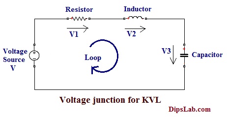
The representation of the Equation is,
For loop, V=(V1+V2+V3)

Where,

V is the total voltage.

V1,V2 and V3 are the drop voltage of the different components.
This is all about Kirchhoff’s Voltage Law.
Applications of Kirchhoff’s Law
Kirchhoff’s Laws are useful for,
- calculating the equivalent current or unknown current.
- determining the voltage drop of the different components of the terminal voltage.
- calculate the value of equivalent resistance or value of the resistance of the different components, etc.
In this tutorial, you have learned about different Kirchhoff’s Laws and applications. It also includes mathematical equations of the electrical circuit.
Ready for online test:
If you are ready to give the online quiz, here is an Electrical Kirchhoff’s Law Quiz.
Thanks for Reading!
Thanks
You are most welcome, Muqtar!
It is very easy to understand. Thank you, mam.
You’re welcome, Vamshi 🙂
Dear Respected Mam,
From above both Kirchhoff’s Laws are working on the principle of Conservation of (Energy or Charge).
Hi, I didn’t get it. Please elaborate your comment.
Thank You Ma’am for such an easy and elaborated detailing of this concept which made it so simple to understand
Really glad, Tanisha to hear this sound.
Love your site perfect one then paid.
Thanks.
You’re welcome:)