Table of Contents
Reactive Power Compensation
There are various ways to control the reactive power in the power system. In the olden days, the synchronous generator is used for reactive power injection.
Nowadays there are technological advancements in these areas as well. Such reactive power compensation devices are:
Passive Reactive Power Compensation
The passive reactive power compensation includes the capacitor bank installation for reactive power injection.
Active Reactive Power Compensation
The active reactive power compensation consists of the use of flexible AC transmission system (FACTS) devices to change the reactive power and active power requirement.
In this article, we talked about the fixed reactive power compensation in the power system.
Let’s study, how to select the capacitor value based on power factor requirement.
Capacitor Bank for Power Factor Improvements
As we know, power factor is the term that is one of the deciding factors for extraction of the magnitude of load current.
The formula for single-phase power is given by:
Power (P) = [V × I × cos(∅)] ..........(1)
Where,
P- Active power
V- Input voltage
I- Load current
cos(∅)- Power factor
We can arrange the power formula for the current requirement.
Current, (I) = [P / ( V × cos(∅))] …....... (2)
As lower the power factor then the system needs to extract more amount of current to meets the required active power demand of the load. This can be clear from formula (2).
Ideally, the power factor is a Unity, but practically it’s very difficult to achieve it. There is a ways to increase the power factor to unity and the use of capacitor bank is one of them.
So, basically reactive power management is useful for maintaining the power factor as close to unity.
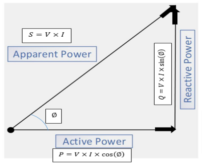
The below power triangle illustration shows the relationship between the active power (P), reactive power (Q) and apparent power (S) and power factor (∅).

Suppose, the load requires the ‘P’ power with some power factor then in this case it will draw some reactive power as well.
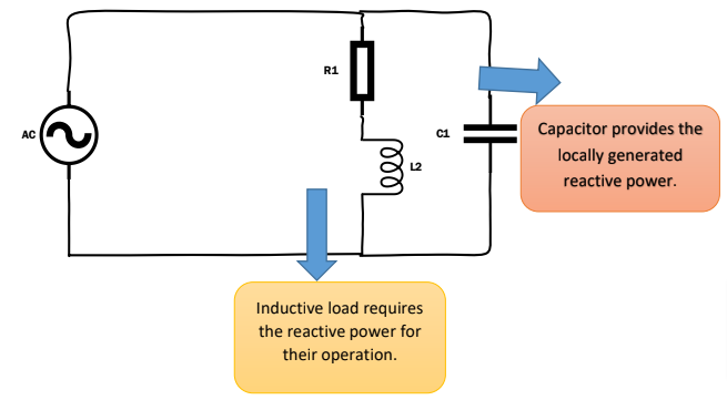
This reactive power demand can be met locally by generating through the capacitor bank so the reactive power burden from the source would be avoided and the corresponding required power factor would also be maintained.
This is shown by simple circuit diagram:

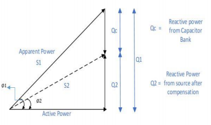
This can be shown by the below phasor diagram with capacitor bank connected at the load end.
The phasor diagram is used for the calculation of the capacitor in the capacitor bank.

The inductive load has a power requirement is ‘S1’ then this can be demonstrated as:
Active Power, P = [V × I × cos(∅1)]

                         = [S1 × cos(∅1)]
For the calculation, you can use handy online power calculator.
- For Single Phase AC System:
[CP_CALCULATED_FIELDS id=”13″]
- For Three Phase AC System:
[CP_CALCULATED_FIELDS id=”14″]
And, also required KVAR is given by-
Reactive power, Q1 = [S1 × sin(∅1)]
Where,
Q- Reactive power
S- Apparent power
- For Single Phase AC System:
[CP_CALCULATED_FIELDS id=”15″]
- For Three Phase AC System:
[CP_CALCULATED_FIELDS id=”16″]
By arranging we get,
Reactive power, Q1 = [P × tan(∅1)]
As we have to increase the power factor from cos(∅1) to cos(∅2) by assuming the constant value of ‘P’ the required KVAR is given by…
Reactive power, Q2 = [P × tan(∅2)]
The generated KVAR of the capacitor bank is given by…
Reactive power, Qc = (Q1 − Q2)

                               = [P × tan(∅1) − P × tan(∅2)]

                               = P [tan(∅1) − tan(∅2)]
Where,
Q- Reactive power from capacitor bank
As we get the required compensation value of reactive power provided by the capacitor bank then we can find out the capacitance of that bank.
Reactive power of capacitor formula,
Reactive power, Qc = (V²rms / Xc)
Where,
‘Xc’ is the Impedance offered by the capacitor.
Impedance, Xc = [1 / (ω × C)]
By putting all these values in the above equation, we get to know about the value of the capacitor.
Capacitor, C = [Qc / (ω × V²rms)]
This is the procedure to find out the rating of the capacitor bank in power factor correction. This ‘C’ value is per phase capacitance value.
This is one of the best solutions for avoiding the penalty due to the lower power factors in the industry.
Read some related articles:
- AC Transmission vs DC Transmission
- Capacitor vs Inductor
- Generator vs Alternator
- Transmission line vs Distribution line
- Single Phase vs Three Phase AC Systems
- Substation Components
- Active component vs Passive component
Thanks for Reading!