In the electricity and magnetism, electric and magnetic field studies are most important. Many similarities and dissimilarities find out in both fields.
Mostly, both fields have a different approach. So, you should know the difference between the electrical field and the magnetic field.
I am explaining more things through the difference between electrical field and magnetic field. These concepts will help you understand both fields.
19 Difference between Electrical Circuit and Magnetic Circuit
Let’s explain the comparison of electric and magnetic fields in tabular form.
| # | Content | Electrical Circuit | Magnetic Circuit |
|---|---|---|---|
| 01 | Basic Difference | In an electrical circuit, electric current flows through the closed path. | In the magnetic circuit, magnetic flux flows through the closed path. |
| 02 | Definition of electric current & magnetic flux | The number of free electrons or electric charge particles that move in the circuit is called ‘Electric Current (I)‘. | The number of magnetic lines of the force passing through a magnet is called ‘Magnetic Flux (ɸ)’. |
| 03 | Unit of current & flux | Electric current is measured in Ampere (A). | Magnetic flux is measured in Weber (Wb). |
| 04 | Circuit Role of electricity and magnetism | In an electrical circuit, electric current flows from positive to negative polarities. | In the magnetic circuit, magnetic flux flows from N-pole to S-pole. |
| 05 | Difference between electric force and magnetic force | In an electrical circuit, an electromotive force (EMF) is used to produce the electric current. Sometimes, EMF is known as electrical potential. | In the magnetic circuit, magnetomotive force (MMF) is used to produce the magnetic flux. Sometimes, MMF is known as magnetic potential. |
| 06 | Unit of EMF & MMF | EMF is measured in ‘Volt (V)’. | MMF is measured in ‘Ampere-turn (AT)’. |
| 07 | Opposition Property of circuits | In an electrical circuit, the resistance (R) opposes the flow of electric current. | In the magnetic circuit, the reluctance (S) opposes the flow of magnetic flux. |
| 08 | Unit of resistance & reluctance | The SI unit of resistance is ‘Ohm (Ω)’ | The SI unit of reluctance is ‘Ampere- turn/Weber (AT/Wb)’ |
| 09 | Flowing Property of circuits | Conductance (G) is the reciprocal of the resistance. | Permeance (P) is the reciprocal of reluctance. |
| 10 | Unit of conductance & permeance | Conductance is measured in ‘Siemens (S)’. | Permeance is measured in ‘Weber/Ampere-turn (Wb/AT)’ or ‘Henry (H)’ |
| 11 | Ohm’s law | According to Ohm’s law of an electrical circuit is, Current (I) = (E/R) = (EMF/R) | According to Ohm’s law of the magnetic circuit is Flux (ɸ) = (F/S) = (MMF/S) |
| 12 | Kirchhoff’s Circuit Laws | For the electrical circuit, Kirchhoff current law (KCL) and Kirchhoff voltage law (KVL) are applicable. | For magnetic circuit, Kirchhoff MMF law and Flux law are applicable. |
| 13 | Kirchhoff’s first law | According to Kirchhoff’s first law of an electrical circuit is, Ʃ(I) = 0, at a node. | According to Kirchhoff’s first law of the magnetic circuit is, Ʃ(ɸ) = 0, at a node. |
| 14 | Kirchhoff’s second law | According to Kirchhoff’s second law of an electrical circuit is, Ʃ(IR) = Ʃ(EMF) | According to Kirchhoff’s second law, of the magnetic circuit is, Ʃ(ɸS) = Ʃ(MMF) |
| 15 | Current density & flux density | Current density (δ) is the rate of the electric currents flowing per unit cross-sectional area of a material. | Flux density (B) is the rate of the magnetic fluxes flowing per unit cross-sectional area of a material. |
| 16 | Unit of the current & flux density | The current density of an electrical circuit is measured in ‘Ampere/square*meter (A/m*m)’. | The flux density of a magnetic circuit is measured in ‘Weber/square*meter (Wb/m*m)’ or ‘Tesla (T)’. |
| 17 | Field intensity of electrical & magnetic circuits | Electric field strength is the electromotive force per unit electric charge. Sometimes, it is known as ‘electric field intensity (E)’. | Magnetic field strength is the magnetomotive force per unit length. It is known as ‘magnetic field intensity (H)’. |
| 18 | Unit of electric & magnetic field intensity | The SI unit of the electric field intensity is ‘Newton/Coulomb (N/C)’ or ‘Volt/Meter (V/m)’. | The SI unit of the magnetic field intensity is ‘Ampere/Meter (A/M)’ |
| 19 | Circuit Structure | The electrical circuit can be a closed circuit or an open circuit. | The magnetic circuit is always a closed circuit. |
Circuit Diagram of Electrical and Magnetic Circuits:
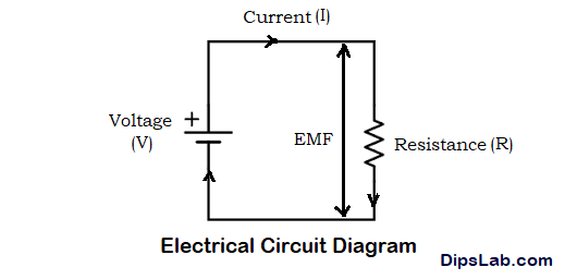
- How does an electrical circuit work?
You can see the following diagram, the resistance is connected in the electrical circuit. This resistance (R) is helped to limit the producing electrical currents (I) in the electrical circuit.

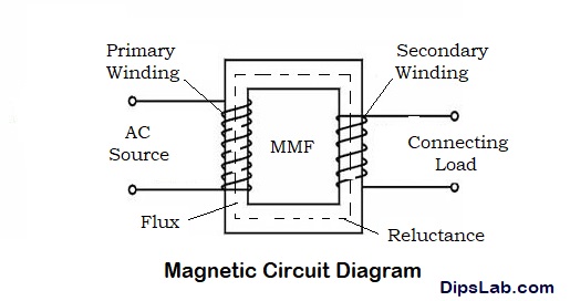
- How does a magnetic circuit work?
The same working function has done. But in the magnetic circuit, we are used reluctance (S) to limit the generating magnetic fluxes (Φ). You can understand from the below figure.

The phenomena of the interrelation of an electric field and the magnetic field are known as ‘Electromagnetism’.
Calculation of different quantities of electrical and magnetic circuits
| Useful Formula | Electrical Circuit | Magnetic Circuit |
| Electrical & magnetic circuits of basic quantities | Electrical current (I), I = (EMF/R) = (V/R) Where, EMF- Electromotive force R- Resistance | Magnetic flux (ɸ), ɸ = (MMF/S) Where, MMF- Magnetomotive force S- Reluctance |
| Opposition quantity | Resistance (R), R = (ρl/a) Where, ρ- Resistivity l- length a- cross-sectional area | Reluctance (S), S = (l/µa) Where, µ- reluctivity l- length a- cross-sectional area |
| Calculation of force of electrical & magnetic circuits | Electromotive force (EMF), EMF= (I*R) Total EMF, Ʃ(EMF) = (IR1+IR2+IR3+…+IRn) | Magnetomotive force (MMF), MMF= (ɸ*S) Total MMF, Ʃ(MMF) = (ɸS1+ɸS2+ɸS3+…+ɸSn) |
| Flowing quantity | Conductance (G), G = (1/R) | Permeance (P), P = (1/S) |
| Formula of current density & flux density | Current Density (δ), δ = (I/a) | Flux Density (B), B = (ɸ/a) |
| Formula of electrical field intensity & magnetic field intensity | Electric Field Intensity (E), E = (EMF/Q) | Magnetic Field Intensity (H), H = (MMF/l) |
These are the important formulae for an electrical and magnetic circuit. For calculating different electromagnetic quantities, you can use online electromagnetism calculator
In this tutorial, I have covered many concepts of the difference between electrical circuit and magnetic circuit. Also, covered dissimilarities and similarities between electric and magnetic fields.
If you have any doubt or any point to include, feel free to discuss in the comment section.
Read some related differences:
- EMF vs MMF
- Resistance vs Reluctance
- Resistance vs Impedance
- Alternating current vs Direct current
- Open circuit vs Closed circuit
- Series circuit and Parallel circuit
- Core transformer vs Shell transformer
Thanks for Reading!
Nice job. Thanks, I am always waiting for your new post.
Thanks, you too Rohit. I am promising that, I will try to cover more technical tutorials/articles.
Helpful article. I have learned and cleared all my basic concepts.
Thanks, Rutvika for your kind word.
Well said mam
Thanks, Vikash
Nice simple presented.
Thank you, Sir 🙂
Thanks, Yuvaraj
Thanks, Mam
You’re welcome, Arman 🙂