
Today, I will explain to you about the Ladder Diagram in PLC programming and different parts of the Ladder Diagram.
There are different standards programming languages defined for Programmable Logic Controller (PLC). Some of the internationally accepted standards are…
- Ladder diagram (LD)
- Structured Text (ST)
- Sequential Function Charts (SFC)
- Instruction List (IL)
- Function Block Diagram (FBD)
Related Read: The explanation of the 5 different types of Programming Languages
Generally, the Ladder diagram is most popular all over the world (including India). This language is easy to learn and it recognizes and looks similar to the electrical circuit diagram.
So I will be focusing only on the Ladder Diagram for PLC.
In this article, I will explain to you more about the Ladder Diagram in PLC programming.
Let’s start with some basics introduction.
Table of Contents
What is the Ladder Diagram (LD)?
The ladder diagram is the universal programming language of PLC. It has a short abbreviation as ‘LD’ and also known as ‘Ladder Logic’.
LD is one of the oldest programming languages for PLC.
In the ladder diagram, the programming language that used to create the program to control the PLC system is known as ‘Ladder Diagram Language’ or ‘Ladder Logic Language‘.
It has signified by the graphical representation, just like electrical wiring for logic control. (At the end of this article, I will share LD examples, that will get you a clear understanding.)
Different Symbols used in Ladder Diagram:
This programming uses different graphic elements. These graphic elements are also called as Symbols.
Basic Important Parts of Ladder Diagram in PLC Programming
- Rungs
- Branches
- Inputs and Outputs for PLC programming
- Addressing Inputs and Outputs
- Instructions
So let us see one by one.
Rungs
What is Rung Ladder?
In Ladder diagram, the horizontal lines called Rungs. You can put as many numbers of rungs as per your project requirements.
And the vertical lines show the power supply or flow.
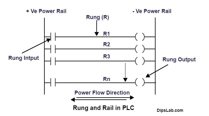
The above diagram is shown with the ‘N’ number of rungs.
Branches
There are three types of branches. They are as follows.
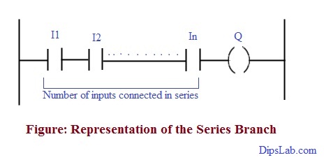
1. Series Branch:
In the series branch, inputs or outputs are connected in the series.
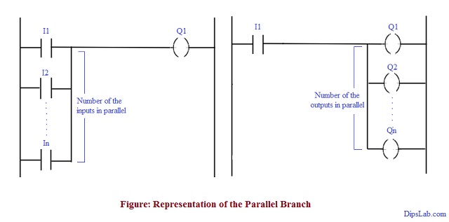
2. Parallel Branch:
In the parallel branch, inputs or outputs are connected parallelly.
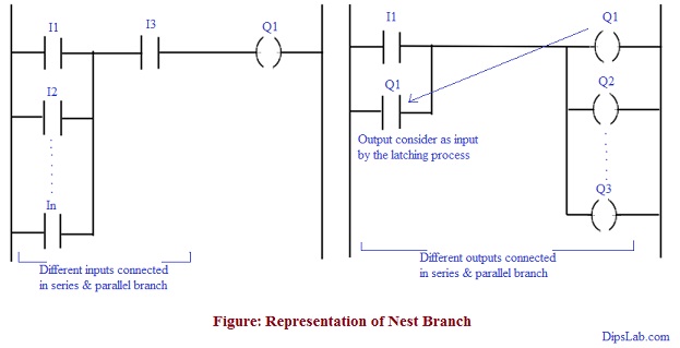
3. Nest Branch:
The combination of series and parallel branches in the same or different rungs are called as Nest Branch.
Inputs and Outputs for PLC Programming:
For writing the program, Inputs and outputs are playing the most important role.
- Inputs refer to the switch or Push Button (PB).
- Output referred to the Coil or Lamp or Load.
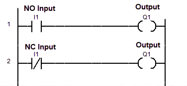
Input is Normally Open (NO) Contact or Normally Closed (NC) Contact.
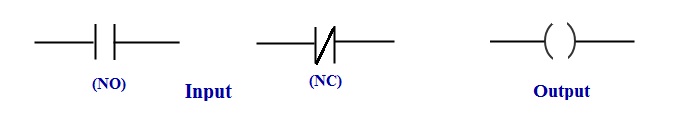
The input and output (I/O) looks in LD programming like-
Addressing Inputs and Outputs
Read Related: Input and Output for PLC programming.
Another next most important thing in PLC programming is addressing of inputs and output for writing the program. Various addressing schemes are used for the different brands of PLC.
Let us take examples from different Brands of PLC
Different Brands of PLC and their Addressing
I explain brands of PLC with their instruction.
1. ABB PLC
The format for the digital I/O address is as below,
- Input Address: I0, I1, I2,…………, In.
- Output Address: Q0, Q1, Q2, Q3, ………….., Qn.
2. Siemens PLC
The format for the digital I/O address is as below,
File types Byte Number.Bit Number
Consider, I/O address for the 1 Byte-
- Input Address: I0.0, I0.1, I0.2, I0.3,……. I0.7.
- Output Address: Q0.0, Q0.1, Q0.2, Q0.3,……. Q0.7.
3. AB PLC
The format for the digital I/O address is as below,
File type: Slot Number. Word Number/ Bit Number
Consider, I/O address for the 1 Byte-
- Input Address: I:0.0/0, I:0.0/1, I:0.0/2, I:0.0/3, ……….., I:0.0/7.
- Output Address: O:0.0/0, O:0.0/1, O:0.0/2, O:0.0/3, ……….., O:0.0/7.
4. Delta PLC & Mitsubishi PLC
In both PLC, the function’s addresses for input, output, and memory are the same. The format for the digital I/O address is as below,
- Input Address: X0, X1, X2, X3……….., Xn.
- Output Address: Y0, Y1, Y2, Y3, ……….., Yn.
Advantage of the Ladder Diagram PLC Language
What are the advantage of the Ladder Diagram PLC Language?
- The ladder diagram (LD) is a simple logic construction and more reliable than an electronic circuit controller.
- Easy to learn and read the program.
- Every programming symbol performs specific actions.
- LD having good representation for discrete logic.
- Easy to troubleshoot.
- Shut down the power without the switch (i.e. hardware devices).
What’s Next?
To understand these aspects more clear, check out the PLC programming example for Running Motor. I have explained it in detail.
Next, go through the rules for writing the PLC program using Ladder Diagram.
This is all from this tutorial about the introduction and different parts of the Ladder Diagram in PLC. I will explain further details in upcoming articles about PLC programming.
Till now, if you are ready for online test, here is a PLC Automation Quiz.
Happy PLC Learning!
Hi, Dipali
For Freshers you have taken very good step so that he can learn basics.You write a topic in a soft learning language. Because six years ago, I was learn PLC programming through internet and reading PLC books. warm welcome to you. Thanks
Arun Siwach
Automation Engineer
Thanks to appreciating me,
My motive to share my knowledge as well as learning more things through this blog.
I’m so glad for shares the blog.
I hope that this blog will be helpful to the learner.
Good information mam
Thanks, Shiva 🙂
Mam, can you guide me how to learn plc programming online.
Hi, Subhradeep
If you want to learn PLC programming from online resources, you will get more stuff.
I have already curated more PLC programming tutorials on DipsLab.com from beginning to end. Here is PLC programming tutorials.
Check here, how to learn PLC programming.
If you follow each and every tutorial step to step, hopefully you can daily learn at your home.
Best material.
Easy and simple
Thank you, Shubham.
can you help me,
I’m also an electrical student,
but I’m confused
Yup, Sure Feroz.
Please, tell me.
What is STL?
STL is a short abbreviation of Structured Text List or Statement List Langauge. This is the textual programming language used for the writing the program in PLC.
Hello dipaliI
I downloaded software Delta WPLsoft, but I did not know how to work with this program as you wrote these led diagrams that you are presenting in this lesson.
Please which program are you explain this lesson
Thank you
very nice publish, i certainly love this web site, carry on it
Thanks a lot to encourage me, Smutstone Astuce. Sure, I will share more tutorials in details.
I must thank you for the efforts you have put in writing this website. I am hoping to view the same high-grade content by you in the future as well. In fact, your creative writing abilities has encouraged me to get my very own website now. 🙂
Input address: I0.0, I0.1, I0.2, I0.3,……. I0.7.
Output Address: Q0.0, Q0.1, Q0.2, Q0.3,……. Q0.7. here I0.0 WHAT DOES IT MEAN(WHAT IS 0 ANOTHER 0 IS WHAT)???
Input address: I:0.0/1, I:0.0/2, I:0.0/3, ……….., I:0.0/7.
Output Address: O:0.0/1, O:0.0/2, O:0.0/3, ……….., O:0.0/7. ALSO SAME LIKE ABOVE
Hi, Shovon
I have already explained an input and output (I/O) address format in this tutorial. This I/O addressing format uses according to the PLC brands’software.
In Siemens PLC, I/O address shows ‘File types Byte Number. Bit Number’ format’.
The first zero(0) represents Byte Number and the second Zero(0) represents Bit Number.
Similarly, In AB PLC, I/O address shows ‘File type: Slot Number. Word Number/ Bit Number’.
The first zero(0) represents slot Number and the second Zero(0) represents Word Number, and the third zero (0) represents Bit Number.
Very nice Mam.
Thanks, Azim 🙂
Thank you so much, Dipali.
I’m glad, you enjoyed it. 🙂