
Everybody knows why time is so important in our life. Whether it is human or machine, nothing can be done without time.
Every little thing around us is getting automated. Here we are interested in PLC (Programmable Logic Controller) automation.
In PLC automation, different types of PLC programming instructions are used with their different specifications.
Out of these PLC ladder diagram (LD) programming instructions, timer instruction is one of the most important instructions which plays a very significant role.
In this tutorial, I am describing the PLC timer in detail with the programming instructions and functions.
Let’s start from the beginning.
Table of Contents
What is the PLC Timer?
PLC timer is a instruction to control and operate the device for a specific duration. With the timer, we can perform any specific operations for a particular time span.
A timer is one of the most essential and useful entity.
You can set time-based activity with the help of the PLC programming timer instruction. Every PLC having different timer functions.
The timer instruction is used to provide programming logic and to decide when to turn on or off the circuit. It has both normally open (NO) or normally closed (NC) contact.
Let’s see here, the representation of the input and output timer NO and NC contact in LD programming.
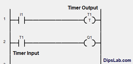
Timer output contact is shown in the coil form or box form or rectangular form. In AB and Siemens PLC, it is represented in the box shape.
If you want to perform work or device activity in a particular time span, you have to get familiar with the timers. For this, you have to learn I/O timer instructions for writing the PLC program.
In the Ladder Diagram (LD) PLC programming, you can set the PLC timer from millisecond (ms) to an hour (hr) time range.
Are you interested in knowing, how does it actually work?
Let’s see the internal circuit of the timer.
Basic Internal Circuit of PLC Timer
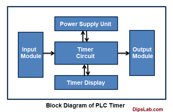
Now, we are looking at the internal timer circuit of the PLC. The working of the timer circuit is based on the four main parts.
Each of the Internal parts of the timer circuit has various features and functions. This is how they are connected and constructed in the given diagram.
Here are some of the basic terminologies you need to understand about timer used in the PLC.
1. Input and Output Modules
The module which interacts with the input signal is called as Input Module. Input module requires to connect to the timer circuit for providing the input signal.
The module which interacts with the output signal is called as Output Module. The output module is required to connect the timer circuit.
Read More: PLC Input Module and Output Module
2. Power Supply Module
The power module provides a power supply for the proper functioning of the timer circuit. It can connect with the ac voltage source (like 120, 230 V AC) or dc voltage source (like 5,12, 24 V DC).
3. Internal Timer Circuit
The timer circuit performs the set and resets functions.
If the auxiliary power supply is ‘on’, the timer will give the momentary input pulse for the set and reset operation.
4. Timer Digital Display
The digital timer displays the set and elapsed timing value.
For the automation purpose, the values can be displayed in a few milliseconds (ms). This will be easy for tracking your automation system.
What are the types of the PLC Timer?
For the ladder diagram programming, the classification of the PLC programming timer is-
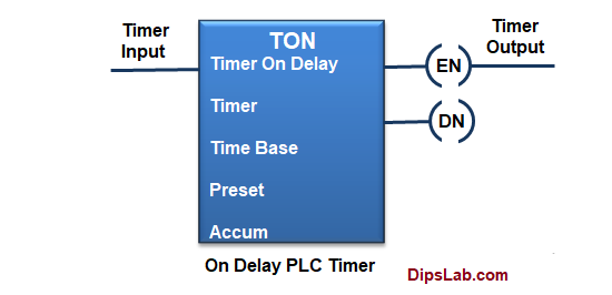
1. On Delay Timer (TON)
An on-delay timer (TON) is a programming instruction which use to start momentary pulses for a set period of time.
Let’s see, a simple construction of the AB PLC On-delay timer programming instruction.
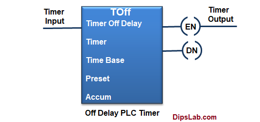
2. Off Delay Timer (TOFF)
A off-delay (TOF) timer is a PLC programming instruction which use to switch off the output or system after a certain amount of time.
See here, a basic structure of AB PLC Off delay timer programming instruction.
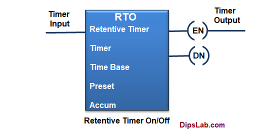
3. Retentive On/Off Timer (RTO)
The main function of the RTO is used to hold or store the set (accumulated) time.
RTO is used in the case when there is a change in the rung state, power loss, or any interruption in the system.
In the AB PLC, retentive timer instruction look like this.
You can briefly read about the each types of PLC timer with an example.
Timer Instructions Address for Multiple PLC Brands
We have seen three timers provide the time delay functions to control the PLC operations. There are four main values that timer deals with.
- Timer Address
- Preset Value
- Timer Base Value
- Accumulated value
Each timer instruction has three very useful status bits. These bits are…
- Enable bit (EN)
- Timer Timing bit (TT)
- Done Bit (DN).
In the AB and Siemens PLC, the output bit is often called the timer’s ‘Done bit’. And it indicates the timer has reached its preset time.
1. Addressing for ABB PLC
In the ABB PLC programming, we can simply write the I/O timer address of the ladder diagram. We can set the timer value in ranges from ‘T0‘ to ‘T255‘.
You can see the above diagram of the I/O contact representation.
2. Addressing for AB (Rockwell) PLC
For the AB PLC, the timer has the address ranging from ‘T4:0′ upto ‘T4:255‘.
Where, T4 is the file type.
Addressing format for timer instruction with the three status bits.
File tpye: Element Number/ Bit status
- Enable bit (EN) address is ranging from ‘T4:0/EN’ upto ‘T4:255/EN’.
- The addressing for Timer timing bit (TT) is ranging from ‘T4:0/TT’ upto ‘T4:255/TT’.
- Done bit (DN) address is ranging from ‘T4:0/DN’ upto ‘T4:255/DN’.
3. Addressing for Siemens PLC
In the Siemens, LD program can be written with the five types of timers.
- Pulse timer (S_Pulse)
- Pulse extended timer (S_PExT)
- On delay timer (S_ODT)
- On delay extended timer (S_ODTS)
- Off delay timer (S_OffDT)
The general block diagram of the timer (In Siemens PLC),
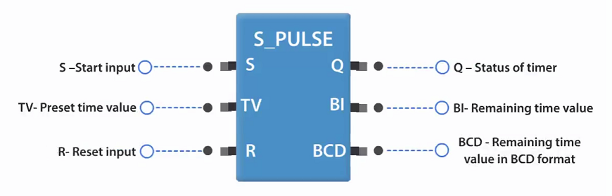
Where,
S – Set value or signal for the timer
TV – Time Variable. It is used to store time value in the form of
S5T#tv
You can enter the time value from 1 to 9990 seconds.
R- Reset value of the timer
Q – Output of the timer
BI – Current time in binary code
BCD – Current time in binary decimal code
4. Addressing for Delta PLC
For the WPLSoft software (Delta PLC), you can use timer addressing ranging from ‘T0′ to ‘T127‘.
In Delta PLC, input timer address is shown like general representation (T0, T1,…….. T127). And Output coil is written in the form of
T(Address rang) K(10*timer value)
Where,
‘T0’ is timer address and ‘K’ is the constant term
Delta PLC timer block diagram:
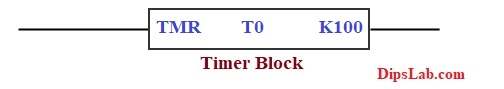
For Delta PLC, the timer starts for a 10-second. It should be written in the form of ‘T0 K100’.
5. Addressing for Mitsubishi PLC
Both, Mitsubishi PLC and Delta PLC, use the same timer addressing format.
Example-based on the PLC Timer Instruction
The very basic and real-life example is controlling traffic signals using PLC automation.
After a certain (fixed) time, each side signal has to turn on and off. At a time only one side traffic signal should be on.
This logic can be implemented using simple PLC timers.
What are the Applications of Timer Instruction?
Here are some of the basics applications of timer you can use in a PLC automation environment.
- Use for the delay action
- It is used to run or stop operation as per the user’s command.
- The RTO timer helps to record or hold an intermediate time value.
This is all about PLC timer. This is a really big topic. I tried to make it simple. If you have any questions, feel free to ask in the comment.
If you are new to the PLC programming, I have shared my thought about how you can master and learn PLC for free.
And if you are ready to give PLC online test, here is a PLC Automation Quiz.
Happy PLC Learning!
Best one…you do great one & your site also very helpful to learn new think easily.
Thanks for visiting my site.
Great
Thank you
Thank you.
Can u tell software for plc programming?
If you are new for the learning PLC, I guess using those free version of any PLC software brand is sufficient for your need.
You can download Delta PLC software from its official website for free.
I have explained the details in the following link-
https://dipslab.com/how-to-learn-plc-programming-free/
RS Logix (AB PLC) and Step 7- Simatic Manager (Simens PLC) are the best software for PLC.
And also, I have shared the 12 brands of PLC with their software. https://dipslab.com/different-plc-software-brands/
Very nice explanation madam
Thanks, Akbar:)
Ok Thanks
Very good for learning.
Thanks, Vijay Sharma.
All time favorite blog for plc.
Thanks,Punit.
Good one
Thank you, Kunal Shah
Thanks
Good work mam.
Thank you, Manavarthi.
Excellent,
Its a wonderful apart from others.
Thank you, Lavkush:)
Hi,
Thank you for your services. It’s really useful. I hope you will share more posts.
Surely, I will publish more tutorials related to PLC.
So many thanks for your time explanation, please continue some more knowledge share.
From- Thi Win, Myanmar.
Thanks, you too for reaching out to my blog.
And I am promising that, I will share more tutorials for DipsLab Reader like you. 🙂
This is an informative article and it’s very useful and knowledgeable.
Thanks, Sumit 🙂
Good explanation, Dipali.
Thanks, Gopal 🙂
Thanks, Mam to share information regarding the PLC timer.
You are welcome, Dear 🙂
Very informative
Thanks, Rajesh.
For any process, delay timers used in PLC programming. Three types of timers are found- On delay, Off delay, and retentive timer.
In Siemens PLC, we have ODT, ODTS, PULSE TIMER, PULSE RETENTIVE, OFF DELAY TIMER.
Right, each timer has different specifications for Siemens PLC.
Great. Usually, we don’t have many number of timers in plcs when we used of ladder diagrams as programming language. I can say- On delay, and Off dealy.
Thanks 🙂
working with codesys myself I would say this was a bit helpful.
Hello mam!
I’m a student of CIPET -IPT LUCKNOW, I’m curious to know new things about machine and their parts. And I learned many things about PLC.
Thank you mam.
I’m very grateful to you
Glad to see that it finds helpful to learners like you.
Great Post!
Thank you! I’m glad you liked it.