
In the programmable logic controller program, mostly the LD programming language is used.
Before writing PLC program in ladder diagram (LD) language, you should be familiar with some basic tips like-
- The basic concept of a logic gate in LD
- PLC Programming rules
- PLC programming Instructions
- PLC Instructions Address
Today I am sharing my article about the PLC ladder diagram program example. Explained in detail.
At the end of this tutorial, you will learn how to write PLC ladder program with a ladder diagram (LD).
Now, let’s start.
Table of Contents
How to Write PLC Ladder Program using a Ladder Diagram?
It is always easier to understand PC programming with the help of example rather than tons of theory.
In the ladder diagram program, the switches are considering as inputs and load are considering as coil or output.
PLC Ladder Diagram Program Example for Running Motor:
Problem Statement: Write a program for a simple motor with the following conditions.
Condition:
Case 1: Following conditions should be satisfied to start a motor.
- Switch 1 is off and switches 2 is on.
- Switch 3 is on or switch 2 is off.
- Both switch 4 and switch 5 are on or switch 3 is off.
- Switch 6 is on or both switch 4 and switch 5 are off.
Case 2: Following conditions should be satisfied to stop a motor.
- Switch I1 is on.
Solution:
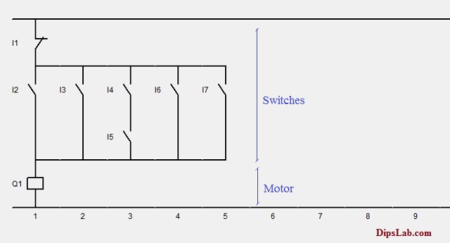
Now, we draw the ladder diagram program with seven switches and a single motor.
As per the below diagram, the switches are representing as I1, I2, I3, I4, I5, I6 and I7. And a coil of the motor is representing as Q1.
The conditions (i.e. On 0r Off modes) of the switches are operated by the toggle button.
First of all, all switches (I2, I3, …., I7) are Normally Open (NO) contact except switch I1.
Case 1: Motor in a Running Condition
Follow the conditions one by one as below.
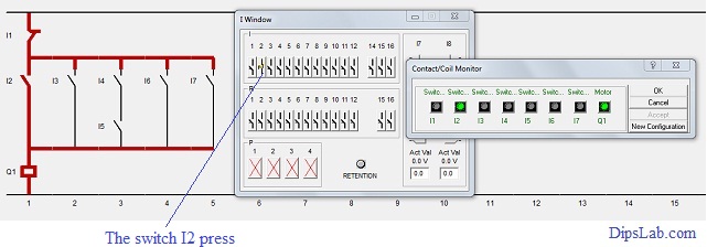
According to the first case, switch I1 has normally close contact.
When you press the switch I2, it gets close contact. This causes the power flowing through the circuit. And the motor starts running.
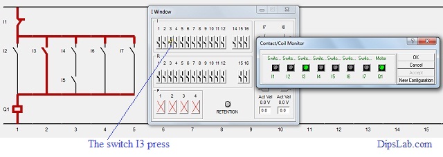
When the switch I3 is pressed and the switch I2 is realized then power flows through the circuit. This makes to run the motor continuously.
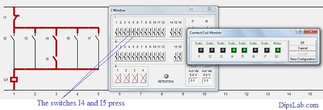
You can see, the switches I4 and I5 are connected in the series.
If both switches I4 and I5 are pressed then it makes the contact (NC) to flow the power. So the motor will run continuously.
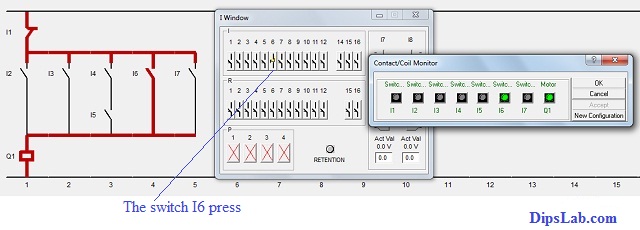
To satisfy the last point in the first case, the switches I6 or I7 should be pressed.
After getting normally closed contact, power continuously flows through to the circuit. Due to this, the motor still runs.
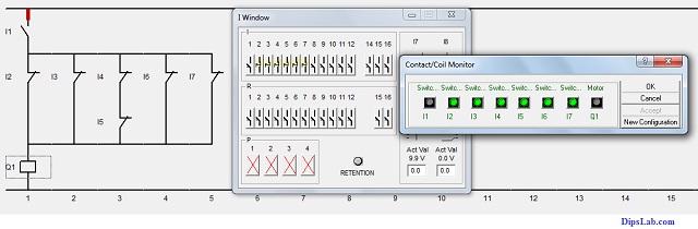
Case 2: Motor in a Stop Condition
If the switch I1 is in NC contact, the switch I1 gets pressed.
Here the switch I1 is in series contact.
After the breaking contact, power will not flow to the motor. So, the motor will stop running.
That’s it all about PLC Ladder Diagram Program example. I have also explained how to write PLC ladder program with images.
What’s Next?
Let’s try to implement logic gates using PLC ladder programming. Logic gates are the most common utility functions in electrical and you will find it very useful in many of the PLC programming projects.
I hope that this article will be useful to learn the basic concept of PLC ladder programming.
Online PLC Quiz:
If you are ready for online test, click on is a PLC Automation Quiz.
If you have any query, let’s discuss in the comment section.
Happy Learning PLC!
I would like to learn PLC. Is it possible without any classes ?
Hello,
Yes, It is possible without class. But, you must know the Gate logic & some important rules for programming.
Because the PLC is totally base on the Logic gate.
I have shared my PLC’s articles on my blog.
I assure these PLC’s tutorials are helpful for learning PLC programming.
For any query about PLC, please frankly ask me. I will be happy helping you any time.
I am not sure about emailing. You can find all the information on this blog.
Hai.
It is very informative with simple examples,
thanks very much dipali. .very use full to the your blog
Thank you!
thanks for sharing informations
i have a question :
the voltage between output of PLC and the contactor coil of motor?
You are most welcome, Abdallah 🙂
Here, o/p of the PLC is 24vdc supply to the barrier and from barrier to contactor gives 230 v Ac supply.
Hi,
Can you share some basic software to be used for PLC ladder diagrams?
Thanks.
Jan Rey
Hello, Jan Rey Cuba.
ABB PLC (AC010 software) is best for learning purpose. If you want to learn LD programming with various features and functions, you can use Delta (WPLSoft software) and AB (RS Logix 5 /500/5000 software) PLC.
Mostly, benefit fact that Delta PLC software is easily available in their site. So, it will be helpful for learning.And also in the before the tutorial, I have shared the list of different brands of PLC with its useful basic software. You can check out.
Can you brief more about profinet protocol?
Yeah, Sure Avinash.
Early as possible, I will share the tutorial on the profinet protocol.
This article is very helpful and beneficial for learner.
Thanks, Anoush leigh 🙂
Very useful info.
I have an interview for Instrument/ICSS engineer coming soon with a company that uses almost all the brands of plc. i dont know anything on plc.
Thanks, Elvis Lgben.
Already, I shared the PLC interview questions tutorial. Hopefully, this tutorial will be helpful for your interview.
All the Best!
what a nice presentation. Thanks, Dipali.
Glad!
Mam , Please share simatic manager v5.6 software download link. Mail ID . sudhakararao43@gmail.com
Hi dear mam,
I am Avinash Chauhan
I have done a master in electrical engineering. Mam, I want to learn about PLC and its industrial examples.
Hi Avinash,
I’m really glad to see your learning interest in PLC.
For learning PLC programming, firstly you should be prepared with the basics and simple guidelines.
Here is a link where I have explained simple steps for beginners.
[Step-by-Step] How to Learn PLC Programming at Home for Free?
– https://dipslab.com/how-to-learn-plc-programming-free/
Hopefully, it might be helpful to you.
thank you very much Dipali. this tutorial makes me love learning about PLC. keep going thanks again.
Thanks, Rediet for reaching out to my blog and finding helpful it.