
Hello,
Today, we are studying the Traffic Control System using programmable logic controller (PLC) programming based on Ladder Diagram.
One of the best use of PLC programming is to control, start and stop the signals in the system.
We saw different PLC software brands. For most of the project work, we use the Allen Bradley (AB) and Siemens PLC brand of PLC.
Because, both PLC software brands provide various/different programming instructions, functions and features.
Table of Contents
[In Detail] Smart Traffic Control System using PLC LD Programming
Let’s find out more detail about the project and project requirement.
Project Requirement
In PLC software, the ladder diagram programming language is used. As a part of this project, we have to write the function of the PLC program which helps us to controls the signal according to the time duration.
This project is based on three different compact PLC software.
Here, we need useful software functions like input (I), output (O), memory (M), and timer (T) for writing the LD program.
These input and output functions consider as switches and lamps in the compact PLC, respectively.
Prerequisite: Basic Parts of Ladder Diagram in PLC Programming
PLC Tools Used in the Project
Tools recruitment are as follow.
- Two Push-Button [PB1 & PB2]
- Three Lamp Signal [Q1, Q2 & Q3]
- One Memory [M]
- Three Timers [T1, T2 & T3]
This is how the LD diagram looks like with these components on ABB PLC.
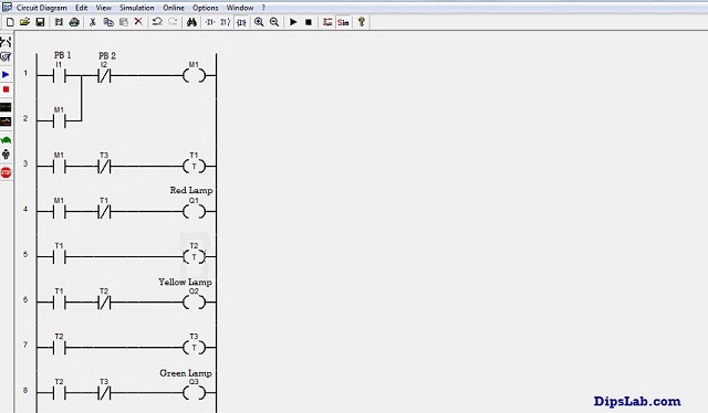
Program on ABB PLC Software
Explaining each connected LD diagram components one by one.
Push-Button [PB]
In the PLC programming, the input (I) expresses as the push button (PB). There are two push buttons- PB1 and PB2. The PB1 (I1) get NO (Normally Open) contact and PB2 (I2) get NC (Normally Closed) contact.
The PB1 is used for the start signal. And PB2 is used for the stop the signal or emergency off purpose.
Both the inputs are connecting with the timers (T).
Output Coil or Lamp [Q]
In the LD programming, there are three outputs (Q1, Q2, and Q3), considered as lamp or output coil.
- The Q1 is considered as the red lamp.
- The Q2 is considered as the yellow lamp.
- And Q3 is considered as the green lamp.
These three lamps (Q1, Q2, and Q3) are connected with the different timers (T1, T2, and T3), respectively.
Memory [M]
It is used for latching process and to store extra energy supply. This memory depicts input or output functions (or coil).
Timers [T]
There are three timers (T1, T2.and T3) is connecting with the three output as per the duration or time requirement. These timers follow delay timer.
- T1 is connected to the red lamp (Q1) for the 5 seconds.
- T2 is connected to the yellow lamp (Q2) for the 10 seconds.
- And T3 is connected to the green lamp (Q3) for the 15 seconds.
Running Program on Different PLC Softwares
You can write a program on the different PLC software. But, you should know the rules of writing LD program.
I have written this traffic control system program on ABB, AB and Delta compact PLC software.
I have already shown the PLC program on ABB software above.
Let’s check the LD program on other two PLC software brands.
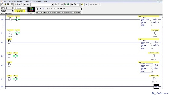
Program on AB PLC Software
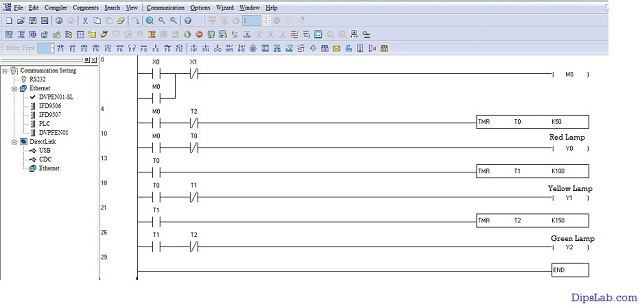
Program on Delta PLC Software
These three (ABB, AB, and Delta) brands of PLC software has the same input and output. But they provide different addresses, features, and functions.
Working of the System
Step 1: When PB1 is pressed, the memory coil gets energized by using the latching process. This memory coil’s supply set the timer T1 for 5 seconds. The red lamp (Q1) gets ON and it glows for 5 seconds.
Step 2: As soon as the timer T1 (NO contact) get NC, timer T2 gets activated. So, the yellow lamp (Q2) gets ON for 10 seconds and the red lamp gets (Q1) OFF.
Step 3: When the timer T2 (NO contact) gets NC, timer T3 gets activated. After that, the time T3 is been set for 15 seconds. The green lamp (Q3) gets ON. red lamp (Q1) and a yellow lamp (Q2) gets OFF.
Step 4: The process continues by using the NC contact timer T3 which is again connected to the first rungs.
Step 5: If any interrupt or emergency occurred, in between, the system will be shut off for the particular duration. This situation is controlled by the PB2.
Result Analysis
- Only Red Lamp gets ON for the 5 seconds.
- When Red Lamp goes off, Yellow Lamp gets ON for the 10 seconds.
- When both the Red Lamp and Yellow Lamp goes off, Green Lamp gets on for the 15 seconds.
This cycling process will continue.
Use cases of This Project in Future
- This project is a small demo to control the signals. To further extend, it can be used for controlling the traffic signal.
- You can tweak the timer and set different times for each signal, based on the traffic on a particular route.
- This simple automation can reduce human interaction for handling the traffic at signals.
- It also reduces the overall cost for controlling traffic single manually.
- Apart from the traffic signal, you can also extend this project for any signal management project where you need to shift the signals after a certain time frame.
This is the simple Traffic Control System using PLC which is done with the help of PLC programming and Ladder diagrams.
You can do or choose any PLC automation project from the list of automation project list.
If you have any query about this topic, please discuss by commenting below. And also share your thoughts about this project.
Thanks for Reading!
Which PLC software should I stick to while learning the ladder diagram language?
Hi Raghu,
In an earlier tutorial, I have covered the topmost PLC brands and their useful software.
As per my experience, I will suggest Delta PLC (WPLSoft) software is best for beginners. WPLCSoft software is completely FREE that available on their Delta official site.
Thank you so much please, I’m a beginner it’s a little tricky but I really want to learn to the best.
You’re most welcome, Macklean.
Thank you very much indeed, i have been struggling for months to find well explained plc tutorials
You’re welcome, Polinema.
Thank you madam. May I ask for your video lecture? If possible than please give me a link.
Sure, Avinash. Here is a video link- https://www.youtube.com/watch?v=zwwBWvB3ugQ. Please check it.
can i get that project
kindly share price & other details
Sorry. This project is not available. But, I can help for LD programming.