
As we all know, logic Gate is a building block for the digital circuit. It takes binary input (0, 1) and gives binary output based on the input provided.
Logic gates using the programmable logic controller (PLC) is the basic thing you must learn if you want to enhance your Electrical and Electronics skills.
In this post, you will be learned to write the programming in PLC using Logic Gates.
For programmable logic controllers (PLCs) programming you need PLC software to build the logic module.
PLC software is a control and input device for writing the programming using ladder diagram programming language…
Table of Contents
Types of Logic Gates using PLC Ladder
Different types of ladder logic diagram that perform different logic gate functions. Basically, there are seven types of logic gates as below.
- NOT Gate
- AND Gate
- OR Gate
- NAND Gate
- NOR Gate
- EX-OR Gate
- EX-NOR Gate
Note: The circuit diagrams are connected to make and break input (I) and output (Q) contact in series and parallel circuits.
For all the circuit diagram, we are representing inputs (I1) and (I2) as switches, output (Q1) as coil/lamp.
Let’s see the explanation for each logic gate with PLC implementation,
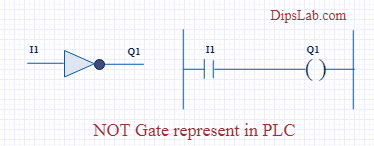
1. NOT GATE
In electronics, NOT GATE is also called an ‘Inverter’ or ‘Buffer’.
Working: NOT gate works as inversion. It takes one input and gives one output. When the input is high then the output is low and vice-versa.
Logic Gate Truth Table for NOT Gate:
| Input (I1) | Output (Q1) |
|---|---|
| 0 | 1 |
| 1 | 0 |
NOT Gate in PLC programming:
In the case of PLC ladder, there will be a push button to provide input. When (I1) is pressed then the coil (Q1) is on. And when Input (I1) is released then coil( Q1 is off.
Symbolic Representation.
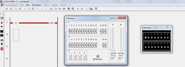
Running NOT Gate ladder diagram program in PLC software.
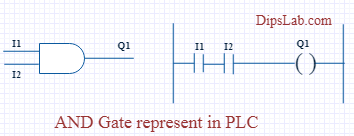
2. AND GATE
Working: In AND Gate, when both inputs (I1 and I2) are high then the output (Q1) will be high. For all other inputs, output (Q1) will be the low.
Logic Gate Truth Table for AND Gate:
| Input (I1) | Input (I2) | Output (Q1) |
|---|---|---|
| 0 | 0 | 0 |
| 0 | 1 | 0 |
| 1 | 0 | 0 |
| 1 | 1 | 1 |
AND Gate in PLC programming:
Using Ladder diagram programming, we are connecting two switches (I1 and I2) as input and coil/lamp (Q1) as output.
In the case of both switches (I1 and I2) are closed, the lamp (Q1) will glow. In another case, if any of the switches (I1 or I2) are open then lamp (Q1) will not glow.
Symbolic Representation as,
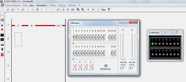
Running AND Gate ladder diagram program in PLC software.
3. OR GATE
Working: If both inputs are low in the OR gate, then the output will be low. For all other cases, the output will be high.
Logic Gate Truth Table for OR Gate:
| Input (I1) | Input (I2) | Output (Q1) |
|---|---|---|
| 0 | 0 | 0 |
| 0 | 1 | 1 |
| 1 | 0 | 1 |
| 1 | 1 | 1 |
OR Gate in PLC programming:
In case both or anyone inputs (I1 and I2) are closed then coil (Q1) will on.
Symbolic Representation as,
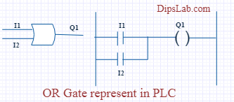
In the above circuit diagram, switch (I1) is pressed then the coil (Q1) will be energized. After releasing switch (I1), the energizing coil (Q1) is providing supply to switch (I2). Then switch (I2) will become automatically activated.
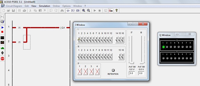
Running OR Gate ladder diagram program in PLC software.
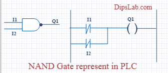
4. NAND GATE
NAND gate is operated as an AND gate and followed by the inverter.
Working: In NAND Gate, the output will be low when both inputs are high. For all other cases, the output will be high.
Logic Gate Truth Table for NAND Gate:
| Input (I1) | Input (I2) | Output (Q1) |
|---|---|---|
| 0 | 0 | 1 |
| 0 | 1 | 1 |
| 1 | 0 | 1 |
| 1 | 1 | 0 |
NAND Gate in PLC programming:
If both switches (I1 and I2) or anyone switch (I1 or I2) are closed, the lamp will be glow. In the case, both switches are open then the lamp will not be glow.
Symbolic Representation as,
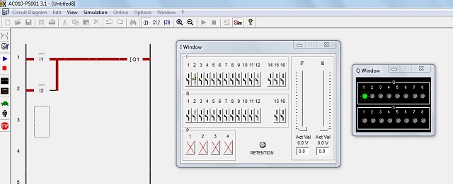
Running NAND Gate ladder diagram program in PLC software.
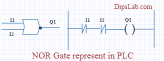
5. NOR GATE
NOR Gate is operated OR Gate followed by the NOT Gate.
When both inputs are low then the output will be high. Otherwise, the low output will occur if both inputs are high.
Logic Gate Truth Table for NOR Gate:
| Input (I1) | Input (I2) | Output (Q1) |
|---|---|---|
| 0 | 0 | 1 |
| 0 | 1 | 0 |
| 1 | 0 | 0 |
| 1 | 1 | 0 |
NOR Gate in PLC programming:
The Coil (Q1) will be activated if both inputs are closed. Coil (Q1) will be deactivated if any one or bothe the inputs are open.
Symbolic Representation as,
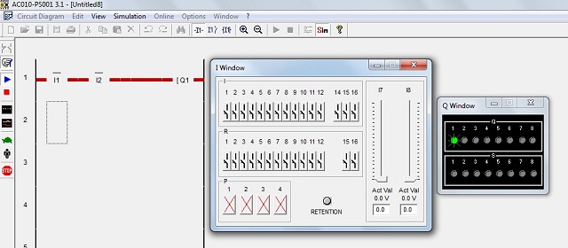
Running NOR Gate ladder diagram program in PLC software.
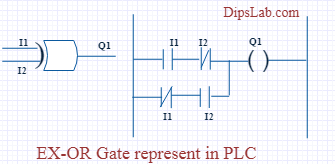
6. EX-OR GATE
Working: If both inputs are high or low, the output will become low. For any other input condition, the output will be high.
Logic Gate Truth Table for EX-OR Gate:
| Input (I1) | Input (I2) | Output (Q1) |
|---|---|---|
| 0 | 0 | 0 |
| 0 | 1 | 1 |
| 1 | 0 | 1 |
| 1 | 1 | 0 |
EX-OR Gate in PLC programming:
In the function of EX-OR Gate, the lamp will be on if one switch is closed and another switch is opened.
Symbolic Representation as,
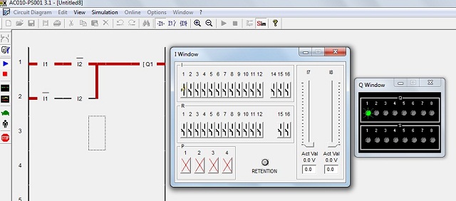
Running EX-OR Gate ladder diagram program in PLC software.
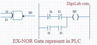
7. EX-NOR GATE
Working: When both inputs (I1 and I2) are high or low then the output will high. If anyone input is high or low then the output will become low.
Logic Gate Truth Table for EX-NOR Gate:
| Input (I1) | Input (I2) | Output (Q1) |
|---|---|---|
| 0 | 0 | 1 |
| 0 | 1 | 0 |
| 1 | 0 | 0 |
| 1 | 1 | 1 |
EX_NOR gate in PLC programming:
The function of EX-NOR Gate, the lamp (Q1) will be on if both switches (I1 and I2) are open or closed. The lamp (Q1) will not be on if anyone switches (I1) is activated and another switch (I2) is deactivated.
Symbolic Representation as,
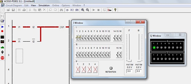
Running EX-NOR Gate ladder diagram program in PLC software.
To Conclude…
This is all about different logic gates using PLC ladder programming. As well as PLC programming rules and programming instructions are also important for writing the program.
Programmable Logic Controller (PLC) Related Topics:
- PLC Automation Companies
- PLC Interview Questions and Answers
- PLC Based Automation Projects
- PLC Automation Training Institutes
Ready for Test:
If you are ready for online test, here is a PLC Automation Quiz.

If you have any question, you can write in the comment section below.
Happy PLC Programming!
The not gate … does it not represent a buffer? Should it not be a normally closed (NC) switch?
Yes that was a typo mainly.
Have a good day.
Everything is fine.
Boss if you give me some diagram using the logic gate for self-practice.
Be well.
Regards
Md Shahjahan
Yup sure, Shahjahan.
Can you suggest to me, Which types of diagram do you want?
Dear madam
Please, can you send me DOL circuit in all languages FBD, STL, LADDER, SFC, and IL for my presentation?
Hi Siddik, it might take some time and currently, I am busy with some other projects. Give me some time. I will share.
How can i get the software AC010-PS001
Hello Sifat, Send me your mail ID.
email ID: sifathossain678@gmail.com
thanks in advance
You’re most welcome!
I also want software AC010-PS001
I think software AC010-PS001 is not freeware. You can download and use delta PLC software as it is easily downloadable and free to use.
email ID: sifathossain678@gmail.com
thanks in advance
Very helpful, i highly appreciate. much thanks for your efforts.
can i get ac010-ps001
egirukwayo@gmail.com
Thank you.
Thank you, Girukwayo Evariste for your kind words.
Even I’m in the same question, not cleared properly.
Please tell me, Rakesh what kinds of help you want?
How do start PLC and SCADA course, please say? I am from Kolkata city.
How can we apply PLC in HVAC?
Hi, I didn’t get a chance to work on the HVAC panel with connecting the PLC. If you want to design this system, you require a technical expert.
This article provides a clear idea with a simple explanation.
Thanks, Rita 🙂
Nice information.
Thanks 🙂
Very useful. If you can also present a simple logic using these gates after describing in words that would have been useful to freshers.
Thank you, Sir.
Sure! Soon, I will explain all PLC programming from basic concepts to solving examples on my YouTube channel.
DipsLab YouTube channel- https://youtube.com/channel/UCr4TGmPBPhZjAUgfoTpcjCA
Dear Dipaliji,
Just seen your website , Very nice information not checked all , Will check all the information , notes if any query will contact you.
Hemant
Thanks, Hemant to visit the DipsLab portal. If you have any queries, you can share on the DipsLab group.
Here is a link to join our Learn PLC SCADA Automation group.
https://www.facebook.com/groups/228416098383863
Hi Dipali,
Can you explain Logic gates in more simple way?
Suraj, I have already explained with the help of PLC software. If you have any queries or doubts, you can freely ask in our automation group. Hopefully, our group expert will assist you.
Learn PLC SCADA Automation –
https://www.facebook.com/groups/228416098383863
Hello mam I have a doubt
Yes, tell me.
I need the AC010-PS001 software
Thank you for reaching out! For the AC010-PS001 PLC software, I recommend checking with the official vendor or the manufacturer’s website for download options and support. If you need any assistance with installation or setup, feel free to ask!