In every system, input and output parts play an important role. The system takes the input, processes it and passes it as output to the other system.
It means that it processes the input data and provides information to another system.
Similarly, input and output modules are the fundamental parts of the Programmable Logic Controller PLC systems.
In this tutorial, I am describing the PLC input and output modules in detail.
Table of Contents
What is the Input and Output Module in PLC?
Multiple inputs (I) and output (O) modules are used in the PLC system. They provide an interface between the central processing unit (CPU) and programmable devices.
What is Input Module?
The module which interacts with the input signal is called as Input Module. It is required to connect input devices like different types of switches.
What is the Output Module?
The module which interacts with the output signal is called as Output Module. The output module is required to connect output devices like electric applications.
Block Diagram PLC Input Output Modules
In the following block diagram, input and output modules are connected through the brain of PLC i.e. Central Processing Unit (CPU).
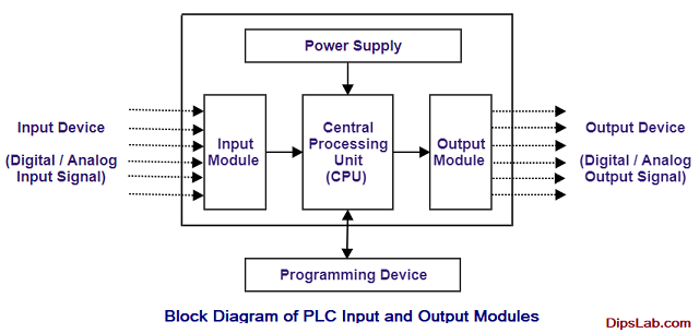
The input device provides a signal to an input module. This input module is connected with the CPU for the initial automated processes. CPU processes all the input data.
After processing by CPU, it gives output data to the output module. The output module provides a signal to the output device. The singles can be anything like activating or deactivating output devices.
And the main function of the programming device is to change or monitor the PLC programming.
There are two types of PLCs- Compact PLC and Modular PLC.
- In Compact PLC, the capability of the I/O module is fixed.
- In Modular PLC, the capability of the I/O module is not fixed.
Classification of PLC Input and Output Modules
The classification of input and output (I/O) modules of PLC is based on the types of signals.
Basically, there are two types of signals- Discrete signals and Continous signals. Based on the signals, I/O modules are classified into two main parts.
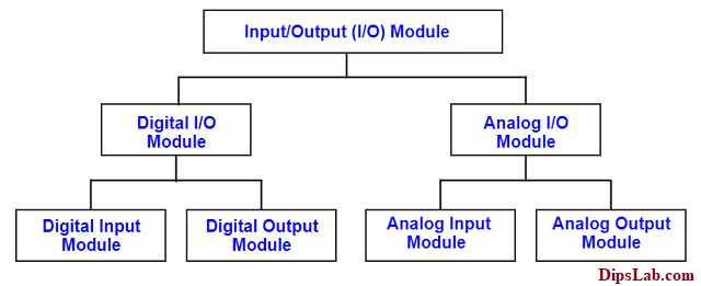
Classifications of the PLC Input Output Modules
1. Digital I/O Module
The digital module is also called Discrete Module.
In this module, the I/O signal work on the binary system i.e. only 0 or 1 value. For the digital input module, only the 1-bit signal is used.
It is useful in the ON or OFF condition.
Based on Input and Output, the digital module is of two types.
- Digital Input Module
- Digital Output Module
The digital I/O signal gives status in the different form like –
- High/Low, True/False and 1/0 for General Status
- ON/OFF for Load Condition
- Activated/Deactivated for Switching Mechanism
- Close/ Open for the Switching Contact Status
Examples: Push switch, Toggle switch, Rocker switch, Selector switch, Proximity switch, Limit switch and etc are the example of the Digital Input Signal.
Examples: Lamp, Coil, Buzzer, Relay, Motor, Fan, Heater, Actuator, Solenoid Valve and etc are the example of the Digital Output Signal.
2. Analog I/O Module
The analog module is called a Continous Module. Usually, the voltage or current is given to the input module in the form of an analog signal. For the analog input module, 12-bit or 13-bit signal is used.
Generally, analog input signals operate in the range of 4-20 mA, 0-20 mA, 1-5 V, etc.
This analog signal provides any intermittent value between the two extreme limits (initial to final range) for the analog input module.
Again, analog I/O modules are also of two types.
- Analog Input Module
- Analog Output Module
Examples: Temperature detection switch, Pressure detection switch, Flow detection switch, Level detection switch, Limit detection switch, Position detection switch, PH Level detection switch are the best example of the Analog Input Signal.
Examples: Temperature Transmitter, Thermocouples, Pressure Transmitter, Flow Transmitter, Level Transmitter, etc., are the example of the Analog Output Signal.
In the PLC system, we can use either digital or analog types of modules as per the project requirements.
These multiple inputs and output modules can be communicated to another system with the help of communication protocols. Check the top 10 communication protocols used in PLC.
Representation of Input-Output Module In PLC Programming
In the PLC programming,
- Input modules are represented by the ‘I‘ or ‘X‘ and
- Output modules are presented by the ‘Q‘ or ‘Y‘.
For the Ladder Diagram (LD) programming language, normally open and normally closed contact is used in the form of input. And the coil or lamp is used in the form of output.
The symbolic representation of I and O modules in the LD program.
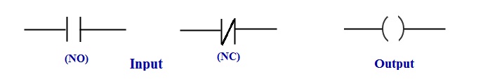
Input and output in PLC LD programming,
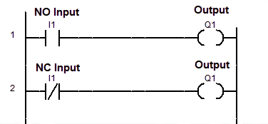
PLC Input and Output Contact
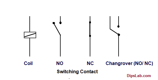
PLC Input and Output Switch
Different PLC brands uses different nomenclatures.
- In AB, ABB, and Siemens PLC, the input is represented by ‘I‘ and output is represented by ‘Q‘.
- But, the input of the Delta & Mitschibushi PLC is represented by ‘X‘ and output represent by ‘Y‘.
Before using input or output, firstly you should be familiar with the input or output rules for writing the ladder diagram PLC programming.
This is all about the basics you should know about PLC input-output modules. I tried to explain it with the help of the block diagram, classification, and examples.
Ready for Test:
If you are ready for online test, click on a PLC Automation Quiz.
If you have any queries related to the modules, you can freely comment on the given section.
Happy PLC Learning!
The examples quoted in Analog Input modules, temperature detection switch, pressure detection switch, flow detection switch, level detection switch, etc., are all of 1/0 signal or one-bit signal connected/used in the Digital input module.
Analog signals representing 4-20 mA, 0-20 mA, 1-5 V, etc., are the signals with 12 bit or 13-bit signals with a resolution of 1/(2**n -1). Examples are Temperature transmitter, thermocouples, Pressure transmitter, Flow transmitter, Level Transmitter, etc.,
Thank you, Sir for sharing this information.
Very Very Thanks
You’re welcome 🙂
Good work.easy to understand with examples… excellent.
Also, add communication module in block diagram representation, nowadays communication module is increasingly being used to monitor and analyze the data’s ( SCADA, IIOT, BMS, EMS, etc)
i.e MODBUS RTU, TCP, PROFIBUS
Thanks for suggesting the topic. Sure, I will add this module with details explanation.
Madam, please send basic learning about the PLC program.
Hi Nithin,
I have curated more PLC tutorials on DipsLab.com. Here is PLC tutorials Link- https://dipslab.com/plc
Kindly, check and refer these tutorials step to step ( from the logic gate, PLC programming rules, etc.).
Generation of PLC.
Sorry. I didn’t get it. What do you mean by the ‘Generation of PLC’?
Very interesting topic, still more of basic PLC for beginners and troubleshooting of LD.
Thanks, Gangadhar.
Thank you, so much keep rock.
You’re welcome.
Your blog is really helpful for beginners. But, I can’t download these all in pdfs.
So, I request to you share these all topics in pdf.
Sorry, Abhishek. I don’t provide the PDFs. But, soon will publish the PLC ebook.
Your blog is so good for beginners, just I have one suggestion that I have searched so many sites for calculation of I/O for plc with some input and output devices. Can you please put any example so we can clear our doubts?
Thanks, Rohankumar for your suggestion. I will try to share more examples. For practice, you can check my previous article where I explained basic examples with diagrams. Here is a article- How to Write PLC Ladder Program
Send the advantage and disadvantage of input module
Sure.
Great Post!