Hello!
I have completed my BE project topic based on – How we can set ‘An Automatic Solar tracking system?’ For which I have used Micro-controller.
Table of Contents
Project Title
“An Automatic Solar tracking system by using Micro-controller”
Project Statement
This project is aimed to developed and builds a chronological Tracking system by using Photovoltaic (PV) module, 8-bit Atmel89S52 Microcontroller, DC gear Motor, L293D Motor drive IC, a Light-dependent resistor (LDR), Analog to Digital converter (ADC) and its Electrical power supply.
Electric Components Used to accomplish Project
Let’s see the useful components for this project,
- Photovoltaic (PV) Module
- Atmel89S52 8-bit Micro-controller
- DC Gear motor
- L293D Motor driver IC
- Light Dependent Resistor(LDR)
- Power supply and other components.
A brief description of the electrical and electronic circuit components used in this project.
1. Photovoltaic (PV) Module
Photovoltaic is the conversion of energy from the sun (light) into electricity. The Photovoltaic module called as Solar panel. or PV module.
It consists of the number of solar cells which are made of semiconductor materials such as Silicon.
These are electrically connected and mounted in the frame is known as Photovoltaic Module.

In solar (PV) cell, when light energy strikes on the module, photons from sunlight knock on the semiconductor material.
If electrical conductors are attached to the positive and negative sides, forming an electrical circuit, the electrons can be captured in the form of an electric current.
PV modules installation is in ground-mounted, rooftop-mounted or wall-mounted. The mount may be fixed or rotating type to follow the sun across the sky.
It is used for grid-connected power generation. We can use an on-grid or off-grid system for the project. If you want to learn more details, you can read the difference between an on-grid and off-grid solar system.
Solar tracker methods have three types as below,
- An Active tracker,
- Passive tracker and
- Chronological tracker.
The solar tracker may be a single axis or dual-axis.
The chronological tracker is a time-based tracking system where it moves at a fixed rate throughout the day (east to west & west to east). This method is a very accurate method.
Advantages: Its operation generates no pollution and no greenhouse gas emissions.
2. ATmel89S52 Microcontroller
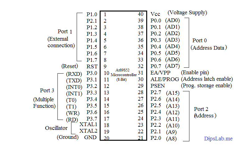
ATmel89S52 8 bit microcontroller is used in this project. It has a total of 40 pins.
Out of 40 pins having 4 different ports P0, P1, P2, and P3. And each port has 8 I/O lines, timer/counters, interrupt, oscillator, ground, power supply.
The 5V electrical power supply provides to the microcontroller for the operation. It is used to perform I/O operations and the execution of the program according to the input signal.
3. DC Gear Motor
DC motors are operated in the steady-state in a speed range. Generally, it has too high-speed So, they need to feedback sensor to allow control of the speed by using DC Gear Motor.
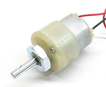
Advantages: Torque and their speed of DC Gear motor are easily control.
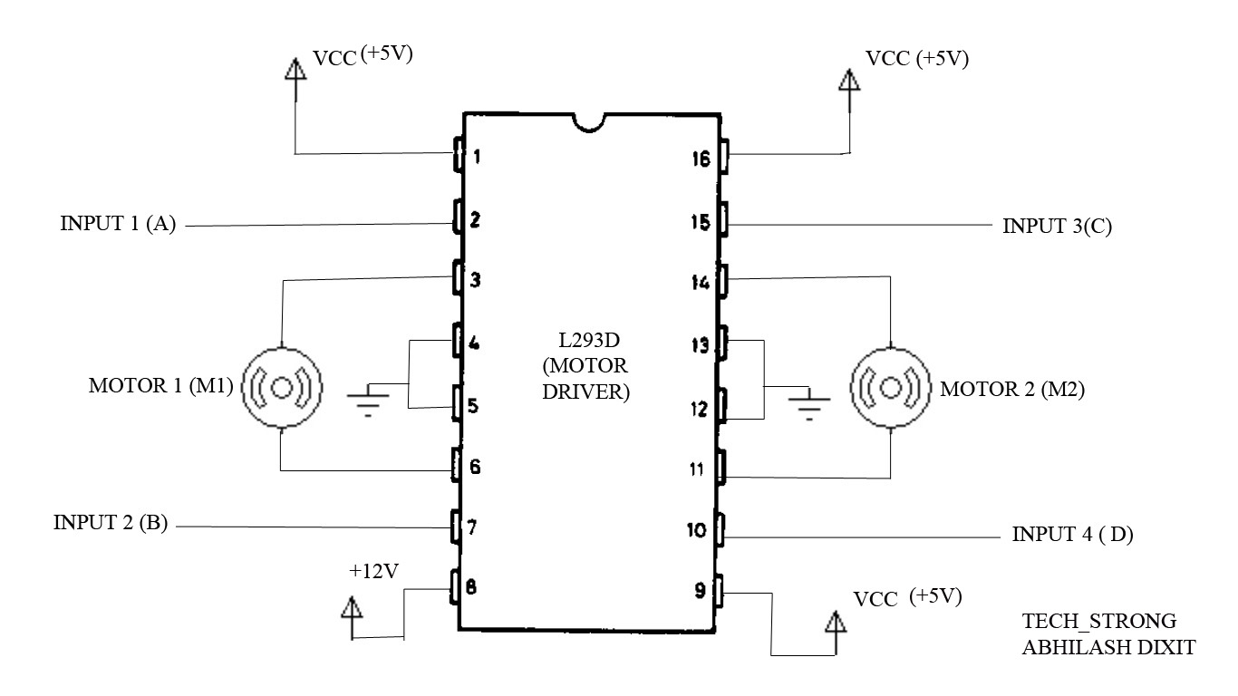
4. L293D Motor driver IC
L293D is a dual H-bridge motor driver IC. It is a total 16-pin IC that can control a set of two DC motors simultaneously in any direction.
The main function of the Motor drive amplifier signal & provide a high current signal.
Out of the 16 pins, two motors are connected to the 4 pins. Pin 2 & 7 on the left and pin 15 & 10 on the right as shown in the below diagram.
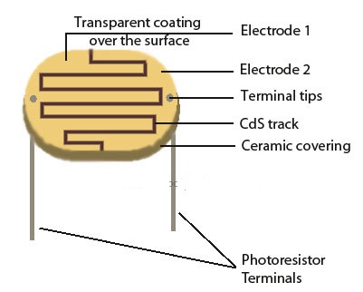
5. Photoresistor
Photoresistor is known as a ‘Light Dependent Resistor‘ (LDR) or ‘Photoconductive cell‘. LDR is made of a high resistance semiconductor like Cadmium Sulfide (CdS) or Gallium arsenide (GaAs).
It is a light-controlled variable resistor. It has provided an analog-to-digital converter (ADC). The ADC converts for the digital signal to the microcontroller.
6. Power Supply
Electrical devices which convert electrical power supplies to the electrical load.
Most are designed to convert high voltage AC mains electricity to a suitable low voltage supply for the electrical load. Ex. 230v Ac supply converted into regulated 5v dc supply to the load.
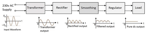
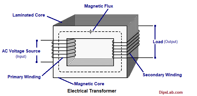
- Transformer
Transformer (especially step down transformer) work with high voltage AC mains to low voltage AC. This low voltage AC output supply connected to the rectifier.
I explained the transformer and its construction in the next tutorial.
Note: As per your project requirement, you can use different types of electrical transformers. And you can buy the transformer for the project.
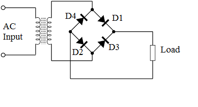
- Bridge Rectifier
Bridge rectifier is a circuit, which converts ac to dc voltage using both half-cycles (positive and negative). The circuit has four diodes connected to form a bridge.
The ac input voltage is applied to the diagonally opposite ends of the bridge.
For the positive half cycle, diodes D1, D3 conduct, and diodes D2, D4 in the OFF state condition. For the negative half cycle, diodes D2, D4 conduct, and D1, D3 are OFF condition.
The conducting diodes D2 and D4 will be in series with the load resistance RL and hence the current flows through RL in the same direction as in the previous half-cycle.
Thus, a bi-directional wave is converted into unidirectional. This output is not suitable without using a smoothing capacitor.
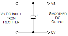
- Smoothing
Smoothing known as filtering. They use to eliminate the ripple factor and provide smoothes the DC voltage supply.
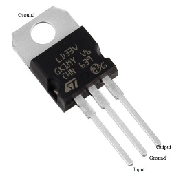
- Regulator
Regulator to regulate the fixed DC voltage by eliminates ripple factor. Voltage regulator IC is available with fixed ( 5V, 12V and 15V) or variable output voltages.
Voltage regulator ICs has 3 pins (input, output, and ground).
A Zener diode is an example of a fixed regulator.
6. Diode
Diode (P-N junction diode) is the component used to control the flow of the current in any one direction. In forwarding bias, the current flows from the P to N junction. It has high current capability and reliability.
The zener diode is used in reverse bias function i.e. N to P junction.
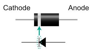
Identification of diode terminal (cathode and anode) by the silver/black line.
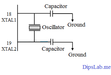
7. Crystal Oscillator
Crystal oscillator is an electronic oscillator circuit that uses the mechanical resonance of a vibrating to create an electrical signal with frequency.
This frequency provides a stable clock signal to the microcontroller for providing the clock signals.
In crystal oscillator circuit has frequencies from a few tens of kHz to MHz. The frequency of the crystals oscillator is measured by counters, oscilloscopes, etc.
8. Transistor
Transistor is a semiconductor device used to amplify and switch electronic signals and electrical power. It has three terminals for connection to an external circuit.
Bipolar junction transistor (BJT) and Field-effect transistor (FET) are the types of the transistor.
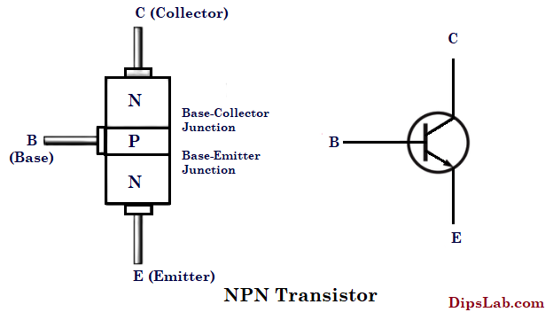
I. Bipolar Junction Transistor:
The bipolar junction transistor (BJT) work as current-controlled devices. This transistor consists of three terminals- Base (B), Collector (C), and Emitter (E).
Under the biasing and current flowing direction, BJT are classified into two types.
- NPN Transistor
- PNP Transistor
Read more: Difference between NPN Transistor and PNP Transistor
For this project, the NPN transistor is used that can control or switch a much larger current between the collector and the emitter terminals.
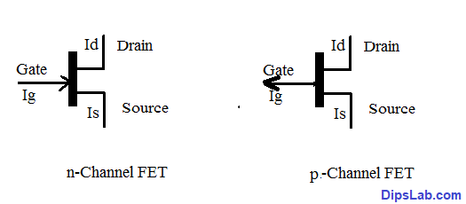
II. Field-Effect Transistor (FET):
A Field-Effect Transistor (FET) is an electronic switching device that controls the device.
Its also know as Unipolar Junction Transistor (UJT). Because it works at single carrier types of operation.
In FET have three terminals Gate (G), Source (S), and Drain (D). Types of FET are Junction field-effect transistor (JFET) and Metal oxide semiconductor field-effect transistor (MOSFET).
These are the explanation of the useful components.
Technical Project Description and Working
Here is the step by step working of Solar Tracking System-
- In this project, time based Chronological solar tracker is used to expose maximum solar energy.
- The solar tracker is automatically oriented in the direction of the high intensity of sunlight with the help of DC gear motor. This will direct the photovoltaic (PV) module from East to West and Back to its initial position.
- PV modules are mounted on DC motor and along with two Light-dependent resistors (LDR). They are fixed at two distinct points.
- When solar energy strikes on the Photo-voltaic (PV) module, the two LDRs are used to measure the intensity of light and vary the resistance depending on the light fall.
- The varied resistance is converted into an analog voltage signal.
- The analog voltage signal is then fed to an ADC. ADC is nothing but analog to digital Converter which receives the two LDR voltage signals and converts them to the corresponding digital signals.
- Then this LDR output (digital signal) is given to the microcontroller. The regulated power supply is given to the Microcontroller for the operation.
- The microcontroller receives the two digital signals data to the H-bridge L293d motor driver IC.
- Then this L293D IC rotates the DC motor at clockwise and anticlockwise direction by corresponding their logic.
- A microcontroller receives the two digital signals from the ADC and compares them.
- Here, the LDR signals are not equal except for the normal incidence of sunlight. When there is a difference between LDR voltage levels the microcontroller program drives the motor towards the normal incidence of sunlight.
This project is an attempt to achieve the following aspects
- Automatic Solar Tracking system for developing a photovoltaic (PV) module with the optimum tracking system with the Sunray.
- The positioning of the photovoltaic (PV) module controlled through the Stepper motor using 8-bit Micro-controller.
- System result for the efficiency of the device, Store the energy, The differentiated with other angle reading by using the electrical measuring instruments.
In An Automatic Solar Tracking System using Microcontroller, hardware and software are used to design a complete project. This is a short summary of the project I have done.
If you have any queries, you can hit the comment on the below section.
Thanks for Reading!
Read the article related solar systems:
- Best Solar Panel
- Uses of Solar Energy
- Benefits of Solar System
- Amorphous Silicon Solar Cell
- Solar Inverter vs. Power Inverter
- On-Grid vs Off-Grid Solar Systems
- Top 10 Solar Power Plants
- Automatic Solar Tracking System Project
I am highly impressed by your work and project. You really put alot of effort and time to gain this.
I will like to meet you.
Thanks, Ezra Kadon 🙂