
Hello Friends!
If you want to excel in Programmable Logic Controller (PLC) programming, then you should know about the rules used in PLC programming.
The different rules are applicable to the different types of PLC programming languages.
Especially, I am explaining these rules for PLC Ladder Diagram programming language with the representation of a ladder language program in PLC.
These rules will helpful for writing the PLC programs.
Table of Contents
6 Rules for PLC Ladder Diagram Programming
Let’s start and follow these PLC programming rules on the based of digital inputs and outputs contact.
Here, you can see the LD program with input (NO and NC) and output contact.
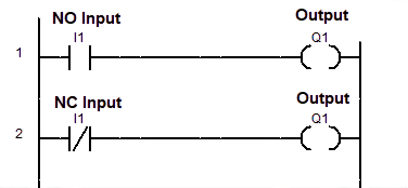
As per your program, you can arrange programming I/O instructions with the help of different programming rules.
1. Inputs can be used in Series as well as Parallel to form a connection
The number of inputs (I1, I2, I3, I4, ……In) can link with different outputs (Q1, Q2,…..Qn) by using series or parallel connection.
In the below figure, the three Inputs (I1, I2, and I3) are connecting in series and four Inputs (I1, I2, I3 and I4) are connecting in parallel with the Single output (Q1 and Q2) respectively.
So we can connect the inputs in series or parallel as per our programming requirement.
Note: In the program, AND gate follows the series connections and OR gate follows the parallel connection. For detail, do read logic gates in PLC ladder programming.
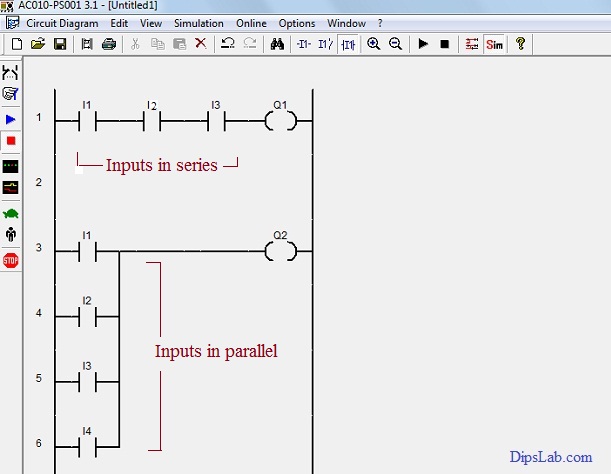
Inputs Representations in Series and Parallel Connection
2. Outputs (or coil) can be used only in Parallel
According to the second rule, outputs (Q1, Q2, Q3, Q4, ……Qn) are connected in parallel along with the single input (I1). Refer to the image below.
If the single input (I1) is normally closed (NC contact) then all outputs (Q1, Q2, Q3, Q4,….Qn) will be activated (On).
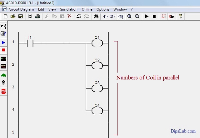
Outputs in Parallel Connection
3. One Input can be used in multiple times in one program
As per the third rule, a single input can be used to repeatedly in the different rungs.
From the below image, the program has different outputs but the same input (switch) connected.
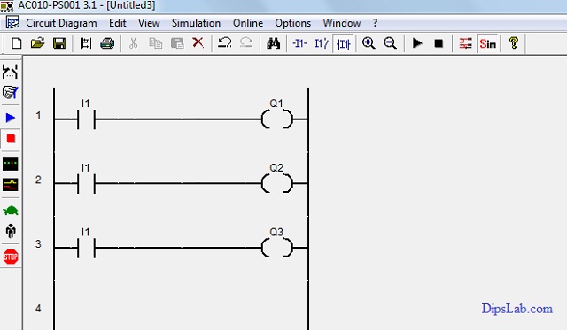
Single Input with a different form of Outputs
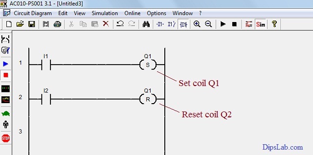
4. One Output cannot be used multiple times in one program, except in Set/Reset and Latch/ Unlatch functions
In the function set/reset, the same output address is used. And it can be connected to the same or different inputs.
As per the below image, different inputs (I1 and I2) are linked with the single output (Q1) using the set and reset function.
When the Input (I1) is pressed, the output coil will be set ( i.e. Q1 on activate mode). And when the input (I2) is pressed, the output coil will be reset ( i.e. Q1 on deactivate mode).
Set Coil or Reset Coil (Same Output Address)
In latch/unlatch function, working is the same as set/reset function. The only difference is, the first input (I1) is normally opened (NO) and the second input (I2) is normally closed (NC).
The lanch/unlatch function is useful for the cycling process.
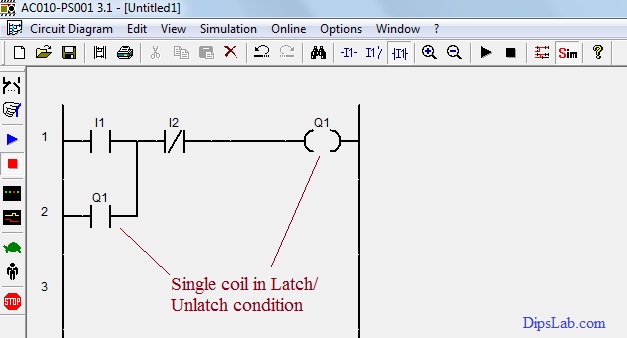
Latch Coil or Unlatch Coil (Same Output Address)
5. Input Address cannot be used as an Output Address
The same input address can be used as multiple inputs. And it can not be used as output.
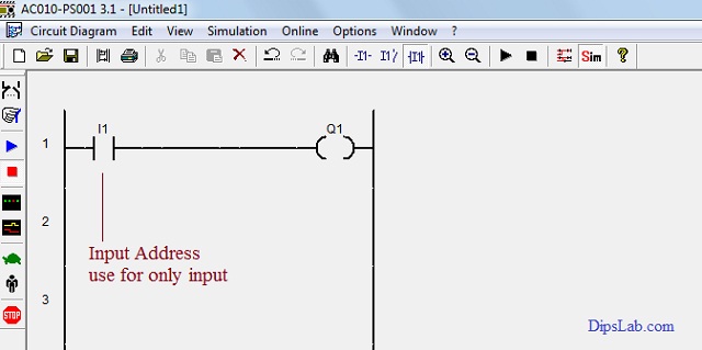
Input Address
6. Outputs Address can be used as Inputs Address
The last rule is for the cycling process (i.e. process continuous from start to end).
In the image below, the output coil works as the input coil with the use of latch/unlatch function.
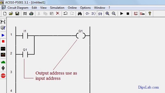
Output Address
So, you can write the PLC program in different ways by using the multiple PLC programming instructions.
That’s it all!
Surely, you will find these rules for PLC ladder diagram programming useful when you start actually working on PLC programming.
Make a practice of following these rules and writing the PLC programs as per your requirements by using the logic gate programming concept.
Ready for Test:
If you are ready for online test, here is a PLC Automation Quiz.
If you have any queries, feel free to start a discussion in the comment section below.
Happy PLC Learning!
I have completed master in Electrical Power System. I work and write technical tutorials on the PLC, MATLAB programming, and Electrical on DipsLab.com portal.
Sharing my knowledge on this blog makes me happy. And sometimes I delve in Python programming.
thank you for you sharing plc ladder diagram, want you contact you through my email
You’re welcome, Tamiru!
Here is my email [email protected] to contact.
Really fantastic helpline ! Terrific
Thank you, Arshad.
This is best article to learn basic think of PLC you will do best platform for learners.
Thank you, Pankaj
thank you so much…..!!!!!!!
You’re welcome, Giri!
This is the best way for express the ladder rule .
Thanks, Sudhakar.
Thanks @Dipali madam…
Your welcome, Salman!
Dipali can you write logic,
There are one start button and one is stop button and two pump flow water through flow meter 50 liter/minute and two selection switch of pump,if one pump is less flow the water than 50liter/minute then automatic second pump is on. At SIEMENS PLC only…..
Thanks for appealing. Actually, I don’t have SIEMENS PLC installed on my system. I mostly dwell into ABB and delta PLC. If I get a chance working on SIEMENS PLC, I will try and share with you.
Thanks, Dipali for sharing it in ladder language. For naive fellows like me, it is easy to digest.
Cheers!
Most welcome Mahesh Mal!
Yup, this is the comfortable language for easy understanding.
Dipali
I wrote first JEE in 1961 & graduated in Electronic engineering. More of physics, amplifiers, Oscillators. Was into the power sector in my business career. Now relearning modern things. Will be asking more questions in due course. First time I am seeing your site. I am 75 years old student now
Sir, you are truly an inspiration to me and to all of us. You defined it again, Age is just a number.
I’m so happy to see you here and there is a lot to learn from you.
Thank you
You’re most welcome, Santosh.
Dipali ma’am, Thank you so much for this blog. It helped me a lot. Once again thank you sooo much.
You are most welcome, Sai Kiran.
Thank you so much Dipali Chaudhari Mam! This blog is very clear and useful.
Thanks, for sharing a few words for blog.
Mam, your side is so good easy to learning and so much helpful for us.
Please, open a YouTube channel and start teaching here.
Thanks a lot, Dibyajit for sharing a few words.
Surely, I will be coming soon on Youtube.
Mam, your side is so helpful.
Mam, do you have any youtube channel?
Does that contain videos on plc and Electrical Ac Circuits??
Hi Gurmeet.
I shared more tutorials on PLC programming from start to end. And I will be coming soon on the youtube channel.
Great Dipali.Exceptionally good.
Thanks, Ajay 🙂
Can you please clarify, why it is suggested to use multiple outputs in parallel only ? As you mentioned in rule no. 2
Thank You
Hi, Ashwini
The multiple outputs can’t be connected with a single input in the series connection of a single rung. Because, we require only a single output with a single input in each series rung.
If you connect the number of series outputs in a single rung then the outputs will become as inputs. Thus, you can use multiple outputs in parallel only with a single input. Otherwise, you can connect multiple outputs with more than one input by using Set-Reset & Latching processes.
Nice 🙂 Very very mandatory Rules.
Thanks, Sanjay.
Very useful
Thanks.
Instead of using inputs multiple times you can use associated memory bits. This would help the PLC to execute the logic faster.
Right, Ashhar 🙂
I think this is good knowledge that you have shared for PLC learners. Any free platform to learn the ladder logic please share.
Thank you.
I have curated more PLC programming tutorials on my online portal DipsLab.com from beginning to end.
Here is the PLC tutorials link- https://dipslab.com/plc
You can use memory bits if inputs get repeated this will save the controller memory. And improve the PLC scan time.
Scan time depends on numbers of Input. Output and number of rungs/ ladder in the program. Lesser the scan time better the PLC.
Yes, all rights. Memory bits use in latching processes.