Hello Friends,
In this article, we are going to study the power components of railway electrification.
This picture depicts the functioning of an Electric Traction.
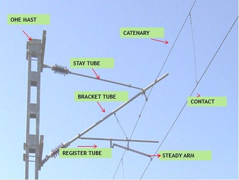
So, whenever you visit the railway station or metro, you observe basically two wires. When the engine arrives, some structure above the engine slides over the wire, this device is called the ‘Pantograph‘.
And the two wires are called ‘Catenary’ and ‘Contact wire’. Both are displaced from each other by small wires called ‘Droppers’.
We would learn more in detail about heights and profiles in the design section.
Let’s first understand where this power supply comes from, how much power supply is needed, the voltage requirement, and other concepts in this article.
Indian railways have adopted a 25KV 50Hz AC supply system for traction power. In some
countries, (for example Spain, France, and many others) use DC power or the third rail concept to power the train.
Why do we need the Traction Substation? Can’t we directly feed power to the Overhead Wires and reduce our costs?
Think over?
The answer to the above lies in case, we provide power directly from the grid. There might be some losses and the train which is 100Km away from the main grid would not receive sufficient power to power the locomotive or may not be able to run at speed due to less current at the end. So, to overcome this we are using a Traction Substation setup to overcome this and also for the safety of life and Electrical Equipment due to any foreseen failure.
These power supplies are derived from the 220/132/110/66kv, 3-phase transmission system from the various grids in the interval of 40-60km distance to the Traction Substation where the level of voltage is reduced to the 25kv by the single phase 21.6MVA Step Down Transformer.
To balance the three-phase loads adjacent traction substation is fed from the different phases in
rotation, For example, 1 TSS AT 0 Km chainage it would be fed from the RY phase other at
40km would be fed by the YB phase, and so on.
Neutral sections are provided in between two adjacent substations to prevent the bridging of
different phases while passing the electric locomotive.
The basic structure of Railway Electrification is divided into three major parts and would study
them individually:
- Power System Installation (PSI)
- Over Head Equipment (OHE)
- Remote Controlling System (SCADA)
Power Supply Installation
Already explained above, the railway receives a three-phase power supply from the authority near the grid substation from where the railway runs its transmission line providing its traction substation.
All EHV and 25KV equipment are owned, installed, operated, and maintained by the supply authority except the 25KV feeder circuit breaker which is owned installed, operated, and maintained by Indian railways.
In case of faults or maintainable high voltage feed to the traction, the substation is fed from double transmission lines which further feeds to 21.6MVA/13.5 MVA ONAN/ONAF transformer one remains in service and the other remains in 100% standby.
Being an electrical Engineer you must be aware of the voltage regulation here the permissible variation in bus bar voltage must be maintained between 10% and 5% implying 27.5KV and 23.75KV and frequency at 48.5Hz to 51.5Hz strictly.
There are various constituents of power systems. I would discuss them in brief in the next articles you might have heard a few of them:
- Substation
- Feeding Post
- Sectioning and Paralleling Post
- Sub Sectioning and Paralleling Post
Thanks for Reading!