
We can not live without water and we can not afford to waste water.
Many times water tank overflows. This is a common issue that happens in our house, hotels, industries, and many more places.
What if you get a notification when the water tank is full so that you can switch off the motor?
I am describing a simple and easy project based on the water tank level indicator alarm system. This system helps to indicate water levels in two different ways.
- It will glow the LEDs at different levels.
- It also starts making buzz sound when tank overflows.
I have recorded a video on my YouTube channels. This is how it looks like.
If you are electrical engineer, you can subscriber to my YouTube channel. I will be posting more of such electrical projects.
This is mini project for electrical engineering students. Let’s see this project in detail.
Water Tank Level Indicator with an Alarm System
On the basis of electrical and electronic equipment, we are building a minor project of water level indicator with the alert system.
This project helps to detect the different water tank levels (like overflow condition, top, middle, and bottom) with the help of three different LED notifications. We can also set the buzzer along with LED.
Let’s see which equipments are required for this project.
Components Used for this Project
For a project, we required multiple electronic components to build the circuit. Thus, I am listing the name of the required equipment with the quantity.
- Three different colors LEDs
- Three 220Ω Resistor
- Four BC547 Transistor
- 9v DC Battery with clip connector
- Buzzer
- Electric Switch
- Zero PCB Board
- Breadboard and Connecting wire (Jumper wire)
You can buy these components from Amazon. Electronic components used in this project does not cost you much. You can try this project at your home.
You can make the circuit by two ways i.e. with soldering and without soldering.
- If you are using zero PCB board, you need a soldering iron for connecting the components and making a circuit.
- You can also make the circuit without using the PCB board. For that, you need a breadboard and connecting wires. You don’t need a soldering iron.
You can choose either way. Here, I’m using the PCB board with soldering iron.
Circuit Diagram of Water Level Indicator System
You can see the following circuit diagram of the water level indicator for the water tank. With this circuit we have connected various electronics components.
Circuit Diagram:
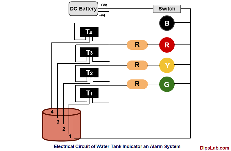
The above transistor (T) terminal is connected with a buzzer (B). And below three transistors are connected to three different LEDs like Red, Yellow, and Green LED through resistors (R).
Electrical Circuit:
After making the connections, this is how the device looks like.
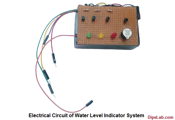
Here,
- The brown board is zero PCB board.
- We have deployed three LEDs on the PCB board.
- There are four transistors (T1, T2, T3 and T4) in black color.
- There is also one buzzer in black color.
Working of Water Level Indicator System
The main function of this project is to detect and alert the system for the particular water tank level. A buzzer helps to alert the system and three different color LEDs indicate different levels like Maximum, Minimum, and Bottom water level.
Let’s see how does the water level indicator work at four different levels.
Look at the above circuit diagram. We have four levels in the water tank.
Suppose, the water tank is empty. And we are pouring water in it.
At first, all the LEDs will be off.
For demo purposes (mini project)., we are using glass instead of a water tank.
1. Green Light Indication (Water Level 1- Bottom):
When the water reaches the first level, the base terminal of the transistor (T1) becomes active. And the green LED glows.
2. Yellow Light Indication (Water Level 2- Middle):
When the water level reaches the middle level (at point 2), the two-transistor (T1 and T2) gets activated. The yellow light will glow.
Both yellow and green light will be ON in the middle level.
3. Red Light Indication (Water Level 3- Maximum):
When the water tank reaches at the top level (at point 3) of the tank. the red light will glow.
At this stage, green, yellow, and red LEDs will glow by activating the three base terminal of the transistors (T1, T2 and T3).
4. Buzzer Indication (Water Level 4- Overflow):
When water overflows from the tank, all-transistor will be active and complete the circuit. Because of the complete closed circuit, a buzzer starts beeping and gives an alert indication to the system.
At overflow condition, all the LEDs will glow and the buzzer will start beeping sound.
This is an automatic water tank level indicator alarm system with a circuit diagram and working explanation. With this simple project, you can monitor the water level in the tank.
Project Related Equipment Detail:
If you have any queries about the project, you can drop me a comment in the below section.
Thanks for Reading!
I have completed master in Electrical Power System. I work and write technical tutorials on the PLC, MATLAB programming, and Electrical on DipsLab.com portal.
Sharing my knowledge on this blog makes me happy. And sometimes I delve in Python programming.
To overcome the water overflow problem, there must be an alarm system to save the water wastage. Water wastage is a common problem in many households or industries and we must reduce the water wastage. While having a water level indicator is a great way that makes a sound whenever the water tank gets full.