
In programmable logic controller (PLC), ladder diagram (LD) programming language is mostly used.
The ladder diagram works as graphical software tools which use for describing and designing electrical circuits.
To design the electrical circuit, we need to know the four basic concepts about ladder logic.
- Branches
- PLC’s Inputs-Outputs
- Instructions and addresses
- Rungs and Rail
In earlier tutorials, I have explained the first three basic concepts of ladder logic.
Now, in this post, we are going to learn about PLC rung and PLC rail with the help of the circuit diagram.
Let’s see what does that meant by Rung in PLC.
Table of Contents
What is a Rung in Ladder Logic?
In PLC ladder logic programming, the horizontal line is called Rung. Basically, the ladder logic is composed of a set of rungs. Each rung represents a single line with specific functions.
Let’s see here, simple representation of the rung in ladder logic.
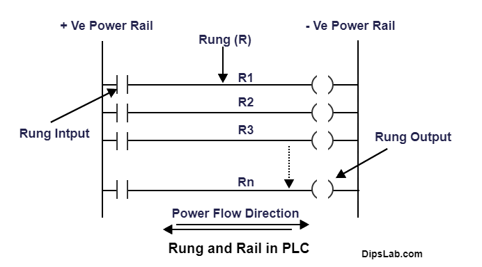
If you have seen the above diagram, the horizontal lines represented as R1, R2 … Rn are the rungs. Each rung can have multiple inputs, outputs, and other programming instructions.
That is how the input and output modules connect and communicate through the rungs.
What is a Rail in Ladder Logic?
From the above diagram, you have seen each rung of ladder logic lies between the two vertical lines. These two vertical lines are called the PLC Rail or Power Rail.
Power rail is used to provide the power source for each rung that makes a complete circuit. It can connect with AC or DC source.
- The left vertical line represents the positive rail (consider as the phase).
- The right vertical line represents the negative rail (consider as the neutral).
Rung Input-Output Representation in PLC
With the help of input and output contacts, we can make or break an electric circuit and to control coils.
PLC Rung Input:
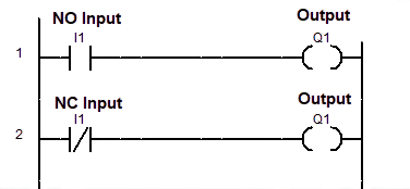
If you are designing an electrical circuit in ladder logic rung, input instruction can be used in two different forms like,
- –[ ]– Normally Open contact (NO)
- –[\]– Normally Closed Contact (NC)
PLC Rung Output:
The rung output contains output instructions in the form of an actuator or coil. In ladder logic rung, PLC outputs represent in two ways.
- –( )– Normally Inactive (NO) Coil
- –(\)– Normally Active (NC) Coil
Rung’s Input and Output representation in Ladder Logic
How does PLC Rung work in Ladder Logic?
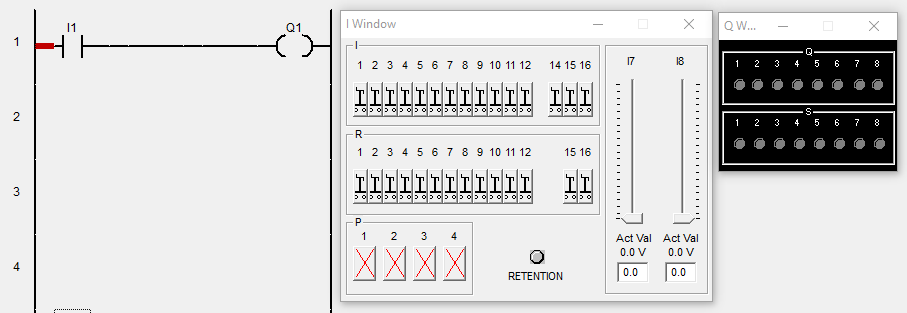
The multiple PLC brand software’s are used for designing the ladder logic circuit. PLC software is also very useful for debugging.
Here, I am explaining the simple example of ladder logic by using the AB PLC software.
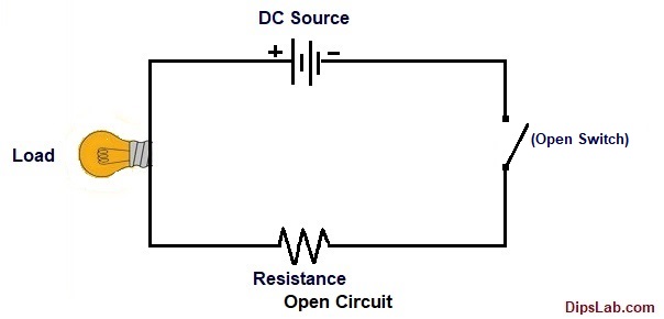
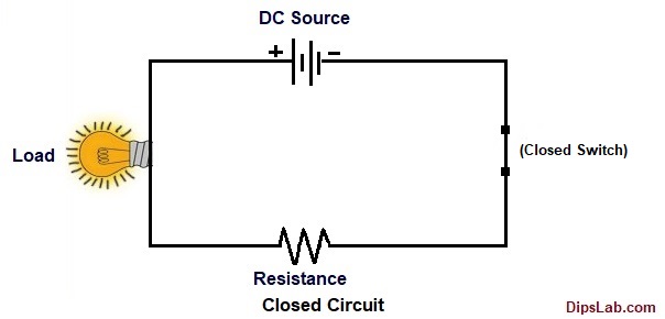
For example, when we design an electrical circuit, we need a power source and connect the load to make a complete circuit or path.
Similarly, if we are designing the circuit in the ladder logic software tool circuit, we require connecting the source as input (as a switch) and load as output (as bulb).
In electric circuit design, single rung contains a single input I1 (Normally open i.e. ‘NO’ or Normally closed i.e. ‘NC’ contact) and the output Q1.
Let’s see in two cases,
Case 1: How does Rung work in NO contact?
- Electric circuit with connected NO switch:
- For Ladder logic (ladder diagram) circuit:
When we connect the normally open (NO) input (I1) with the output coil (Q1), electric current does not flow in the rung.
Thus, ladder logic rung will not be active or online mode. And output or coil (Q1) will not be activated.
Case 2:
- Electric circuit with connected NC switch:
- For Ladder logic (ladder diagram) circuit:
When we connect the normally closed (NC) input (I1) with the output coil (Q1), an electric current flow in the rung.
Thus, ladder logic rung will work in active or online mode. And output or coil (Q1) will get automatically ON condition.
You can see the following diagram where rung show in red color line (active or online mode).
Each PLC rung executes the program from left to right and vice-versa. Also, PLC program executes through the each rung from top to bottom and vice-versa.
You can put as many numbers of rungs as per your circuit design requirement and PLC automation projects.
If you have any quires, you can freely ask with me by commenting. If you find this tutorial helpful, kindly share.
Ready for Test:
If you are ready for online test, click on is a PLC Automation Quiz.
Happy PLC Learning!
I have completed master in Electrical Power System. I work and write technical tutorials on the PLC, MATLAB programming, and Electrical on DipsLab.com portal.
Sharing my knowledge on this blog makes me happy. And sometimes I delve in Python programming.
Nice Blog. Keep writing and educating.
Thank you for sharing!
Thanks, you Gaurav for reaching out to my blog 🙂
Very useful. Thanks Dipali Chaudhari.
You’re welcome, Bhushan 🙂
Thanks for sharing.
Glad!
Only ladders, no snakes.
Our first rung of PLC knowledge. Nice to see!
Thank you
Love this.
Thanks, Vaibhav 🙂
Thanks for sharing.
You’re welcome 🙂
Thank you for sharing. I’m more curious about PLC. Dipali can you guide me?
Really, I am very glad to see your interest for PLC learning. Kindly, check here more PLC programming tutorial from beginning to end.
Link- https://dipslab.com/plc/
Sure, Ghanshyam. I will always ready to assist you. If you have any queries, you can join and share on our Learn PLC/SCADA Automation Group.
Nice blog. Thank you for sharing.
Thanks, you too, Sagar 🙂