
In an earlier tutorial, we have studied timer instruction with their types. In this tutorial, we will learn the PLC counter with a detailed explanation.
Let’s start from the beginning.
Table of Contents
What is the PLC Counter?
We can define the counter in PLC programming as…
an instruction which is useful for sequential counting as digital signal pulse or the number of digits.
This instruction is denoted by the ‘C‘ in LD programming. And it is part of the mathematical function.
The role of the counter in PLC is to control and to operate the device in the sequential order. This sequential order can be in ascending order or descending order.
There are two attributes associated with the PLC counter instruction.
- Counter Limit
With this limit, we can set the range of the counter. - Current Counter Value
This depicts the current value of the counter.
How PLC Counter Works [Block Diagram]
The basic internal counter circuit requires auxiliary power supply (APS), an input-output terminal, a counter circuit, and a digital display.
You can see PLC counter internal structure as given block diagram with their specific connected parts.
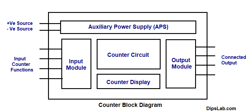
Each of the Internal parts of the counter circuit has various features and functions.
Note: The timer and counter in PLC are two different things. Let’s see how these two are different.
Difference Between timer and counter in PLC
Both have the same function of programming instruction to control and to operate the device. But the main difference in between is-
- Counter counts the sequential digital pulse in binary form.
- Timer counts and controls the operation based on time intervals.
PLC timers and counters can be used as LD programming instructions.
Counter in LD Programming
Ladder diagram programming language consists of the multiple functions of programming instructions.
Let’s take an example of ladder diagram where we are implementing ABB PLC counter.
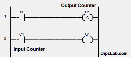
Input counter contact is shown using two vertical parallel lines.
Output counter contact is shown in the coil form or box form or rectangular form. In AB and Siemens PLC, it is represented in the box shape.
What are the types of the PLC Counter?
Basically, PLC counter operates into four modes such as up mode, down mode, bidirectional mode, and the quadrature mode.
Counters in PLC are classified into three main different parts.
- Up Counter (operates up mode)
- Down Counter (operated in down mode)
- Up/Down Counter (operates in bidirectional and quadrature mode)
Let’s see the counter and their mode one-by-one.
1. What is a Up Counter?
Up counter counts from zero to the preset value. Basically, it increases the pulse or number.
Up counter is known as the ‘CTU’ or ‘CNT’ or ‘CC’ or ‘CTR’.
Up counter function block diagram:
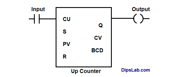
We can also set the initial and target value as an input to the counter.
Here, the up-counter in PLC can count the value from the initial value to the target value. This initial value must be less than the target value. Most of the time, it is set as zero.
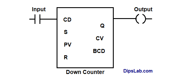
2. What is Down Counter?
The down counter counts from the preset value to zero. It decreases the pulse or number.
Down counter is shortly known as the ‘CTD’ or ‘CD’.
Down counter function block diagram:
The down counter counts from target value to the initial value by decreasing it. This initial value must be less than the target value.
3. What is Up-Down Counter?
The up-down counter counts the value from zero to the preset value or from the preset value to zero.
In other words, this counter can be act as down counter or up counter.
Up-down counter is known as ‘CTUD’.
For the bidirectional and quadrature operation mode, the up-down counter is selected depending on the status (high or low) of the specified count input terminal.
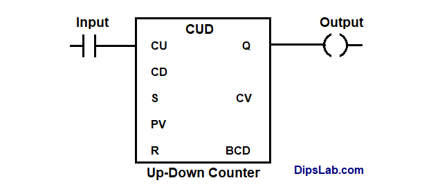
Up-down counter function block diagram:
In PLC programming, the up/down counter instruction is mostly used for the increment and decrement counting pulse or units.
Counter Instructions Address for Multiple PLC Brands
1. Counter Instruction Addressing for ABB PLC
In the ABB PLC programming, we can simply write the I/O counter address of the ladder diagram. We can set the value in ranges from ‘C0‘ to ‘C9999‘.
2. Counter Instruction Addressing for AB (Rockwell) PLC
For the AB PLC, up-counter and the down counter are used in LD programming.
Addressing format for timer instruction with the three status bits:
File type: Element Number
Counter instruction address is ranging from the ‘C5:0‘ up to ‘C5:255‘.
3. Counter Instruction Addressing for Siemens PLC
In Siemens PLC, up, down and up-down counters are used. These three PLC counters require some important factors
- S – Set the value of a counter.
- Q – Output of the counter.
- R- Reset value of the counter.
- PV- Preset counter value.
- CV – Count Variable.
- BCD – Current count in binary decimal code.
Preset counter value (PV) and Count variable (CV) require the same addressing format. The standard addressing format of the PV and CV in LD.
C#Counting Value
4. Counter Instruction Addressing for Delta PLC
For the WPLSoft software (Delta PLC), you can use counter addressing ranging from ‘C0′ to ‘C225‘.
In Delta PLC, the input counter address is shown like general representation (C0, C1, C2,……..,C225). And the output shows in the standard form of-
[CNT C0 K*(Count number)]
Where,
‘C0’ is counter address range and ‘K’ is the constant term.
Also, the two categories counter instruction are widely used,
- Increment (INC) Type Counter
- Decrement (DEC) Type Counter
Both types of counter are selected for counting the digital pules or number of events in a specific order i.e. increment and decrement order.
Increment counter works like the up counter mode operation. The standard format of the increment type counter is,
[INC D*(Count value)]
Decrement counter use instead of the down counter. The standard format of decrement type counter is,
[DEC D*(Count value)]
Where, D for the integer value. You can choose any value like float value.
5. Counter Instruction Addressing for Mitsubishi PLC
In the GX Works2 software, Mitsubishi PLC counter instruction is used in the addressing form of,
C*(Address range) K*(Counter value)
Summary of PLC Counter Function
- The basic counter function is to count the digital signal pulse or binary system.
- Different PLC brands offer a different range of counter values.
- Counters work as per the supported mode.
- Counter operates in up mode, down mode, bidirectional mode, and quadrature mode.
- Up counting starts from the zero or initial value to the target value.
- Down counting starts from target value down to the initial value.
We can also reset the counter.
What is Reset Counter Function?
Reset counter function is to set the counter back to the initial or normal state. If you want to start the counting from the initial value, you can use this function.
In case of digital pulse counting, reset counter functions work differently for up and down counter.
- For up counter, reset counter function sets the pulse or value back to a lower value.
- For down counter, reset counter function sets the pulse or value back to a higher value.
This is all about PLC counter. This is a really big topic. I tried to make it simple. If you have any questions, feel free to ask in the comment.
If you are new to the PLC programming, I have shared my thought about how you can master and learn PLC for free.
And If you are ready to give online test, here is a PLC Automation Quiz.
Happy PLC Learning!
I have completed master in Electrical Power System. I work and write technical tutorials on the PLC, MATLAB programming, and Electrical on DipsLab.com portal.
Sharing my knowledge on this blog makes me happy. And sometimes I delve in Python programming.
Too nice.
Thanks, Rohan 🙂
Love this.
Thanks 🙂
Informative, article.
Thanks, Komal 🙂
Love your name as well as your vast knowledge of PLCs. I am currently writing a technical Lesson Plan on PLCs for presentation to an international testing organization. Your articles have corrected some of the misconceptions that I originally had about PLCs. Thank you very much!